


DI–720/DI–722/DI–730 Series User Manual
Getting Started
8
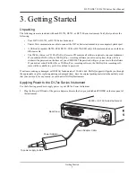
2.
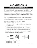
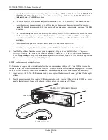
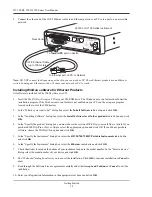
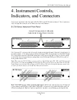
Plug the appropriate end of the supplied power cord into the power adapter and the other end into any standard
120VAC, 60Hz, single-phase outlet. If an alternate power source is to be used, refer to the following pin-out dia-
gram for power requirements:
3.
Turn the POWER switch on.
Printer Port Instrument Installation
All DI-7xx Series instruments can use your computer's parallel (or printer) port to interface digital and analog signals
to your computer. Ethernet/USB models provide Ethernet or USB communication ports (cannot be used concurrently
with the printer port).
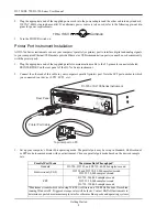
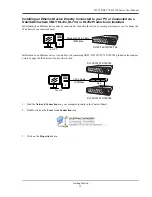
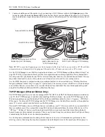
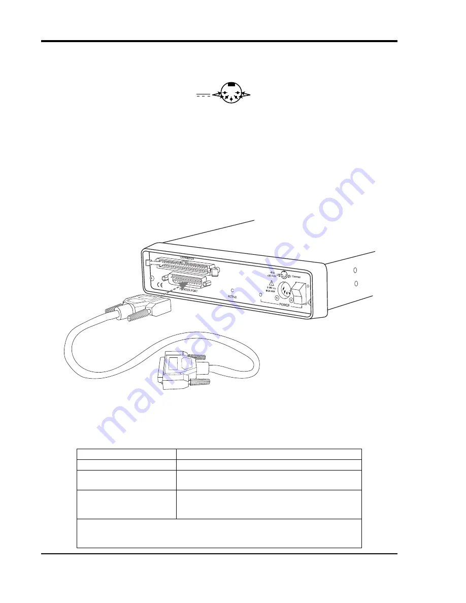
1.
Plug the appropriate end of the supplied parallel communications cable to the 25-pin male connector labeled
PRINTER PORT on the rear panel of the DI-7xx Series instrument.
2.
Connect the other end of this cable to your computer's parallel (printer) port. Note the LPT port number to which
you connected your device (LPT1, LPT2, etc.).
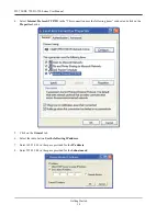
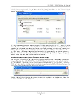
3.
Set up your computer’s Printer Port operating mode. The parallel port may be set up in Standard, Bi-directional,
or EPP mode to communicate with your instrument. Choose a parallel port mode based on the desired sample
rate:
Parallel Port Mode
Maximum Data Throughput*
Standard
DI-720, DI-722, and DI-730: 40,000 samples/second
Bi-directional (PS/2)
DI-720 and DI-730: 80,000 samples/second
DI-722: 50,000 samples/second
EPP
DI-720: 200,000 samples/second
DI-722: 50,000 samples/second
DI-730: 150,000 samples/second
*Maximum stream-to-disk rate using W
IN
D
AQ
software on a 350 MHz Pentium II machine
running Windows 98. Triggered storage rates will be faster. Contact DATAQ Instruments to
determine expected maximum sample rates for other machine speeds and operating systems.
+9 to +36 V
Common
To printer port on PC
Rear Panel
Printer Port Cable
DI-720 or DI-730 Series Instrument
Summary of Contents for DI-725/E
Page 2: ......
Page 4: ......
Page 6: ......
Page 10: ......
Page 32: ......
Page 40: ......
Page 45: ...DI 720 DI 722 DI 730 Series User Manual Block Diagram 35 6 Block Diagram DI 720 Series 1 32...
Page 46: ...DI 720 DI 722 DI 730 Series User Manual Block Diagram 36 DI 722 Series...
Page 106: ......
Page 107: ......


