A-Class
85
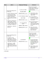
5.3.2 Burn Line Adjustment
Adjust the Burn Line only after trying suggestions in Sections 5.3.1 and 3.5 to achieve print
conformance and aesthetic standards. If print quality remains unacceptable, adjust the Burn Line
as follows:
If you have questions regarding this procedure, contact a qualified technician or
Datamax-O’Neil
Technical Support before proceeding.
1.
Load media (and ribbon, if required), as described in Section 3.1.
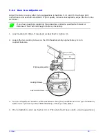
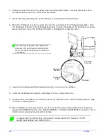
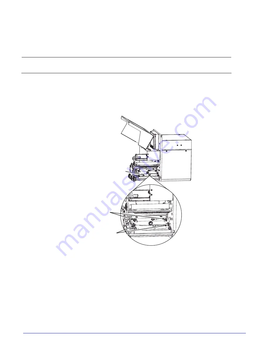
2. Loosen the two Locking Screws on the Printhead Assembly approximately ¼ turn
counterclockwise.
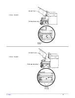
Printhead Assembly
Locking Screws
Adjustment Screws
3. Turn the Adjustment Screws counterclockwise to bring the printhead burn line (see illustration,
Section 5.6.1) forward (in the FEED direction) of the top of the platen.
4. Print a Validation Label; see Section 4.3.4. (
The label should have a light, uneven appearance.
)
Summary of Contents for A-Class Mark II
Page 1: ...Operator s Manual ...
Page 2: ......
Page 5: ......
Page 20: ...10 A Class Peel Point Dimension See Appendix C for the PE Series printer s dimension Peel Bar ...
Page 80: ...70 A Class ...
Page 113: ...A Class 103 ...
Page 115: ...A Class 105 ...
Page 126: ...116 A Class ...
Page 134: ...124 A Class ...
Page 138: ...128 A Class ...
Page 142: ...132 A Class ...
Page 156: ...146 A Class ...
Page 158: ...148 A Class ...
Page 164: ...154 A Class ...

