14
A-Class
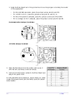
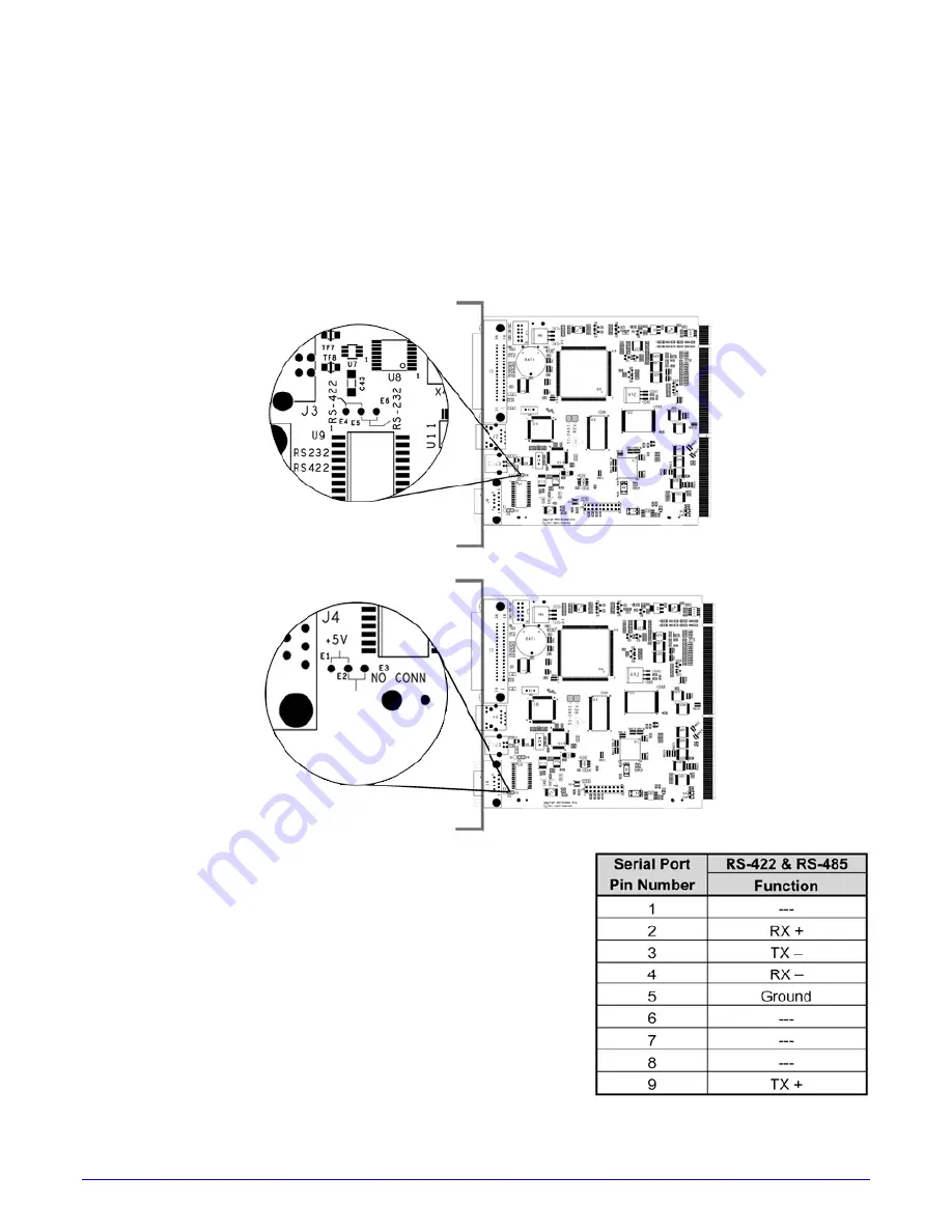
3. Slide the Main Board out of the printer then move the jumpers according the needs
of the application:
•
For RS-422/485 operation, place the jumper across pins E4 and E5;
•
For +5VDC on Pin 1, place the jumper across pins E1 and E2; or,
•
For RS-232 operation (default), place the jumper across pins E5 and E6;
•
For no voltage on Pin 1 (default), place the jumper across pins E2 and E3.
Communication Jumper locations:
+5 Volts Jumper location:
4. Slide the Main Board into the printer and secure it
with the two previously removed Screws.
5. Connect communication cables to the Main Board and
plug in the power cord
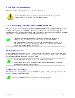
For RS-422/485 communications, ensure that your cable
meets the requirements (per the table, right) for proper
data transfer.
Summary of Contents for A-Class Mark II
Page 1: ...Operator s Manual ...
Page 2: ......
Page 5: ......
Page 20: ...10 A Class Peel Point Dimension See Appendix C for the PE Series printer s dimension Peel Bar ...
Page 80: ...70 A Class ...
Page 113: ...A Class 103 ...
Page 115: ...A Class 105 ...
Page 126: ...116 A Class ...
Page 134: ...124 A Class ...
Page 138: ...128 A Class ...
Page 142: ...132 A Class ...
Page 156: ...146 A Class ...
Page 158: ...148 A Class ...
Page 164: ...154 A Class ...


