


Operating Mode
Reference Manual
57
Active Closed: The input is active when current flows through IN pins. The input
from the trigger source is normally opened. The scanner goes into trigger mode
when the input source is closed.
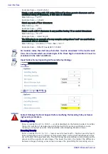
Stop Phase Edge
Select Trailing or Leading from the drop-down list to define the signal edge of the
stop input used by the scanner as reference for ending the reading phase:
Trailing: The reading phase ends when the pack has completely passed by the stop
input.
Leading: The reading phase ends as soon as the stop input detects the front edge
of the package.
Trigger Debounce
Enter a value in milliseconds that specifies the debounce time of the trigger input
signal.
This amount of time is the minimum amount of time in milliseconds the photo
detector should be blocked to be considered an object to scan, reducing false
triggers. A typical value is 5 msec. This value must be significantly less than the
amount of time from the trigger to read line.
Trigger Source: Serial/Network
In Serial/On-Line mode the reading phase starts when the Serial Start String is
received on the serial interface and ends when the Serial Stop String is received or
when a programmed Reading Phase Timeout expires.
If decoding is correct, the data is transmitted on the serial port as defined by the
configuration. The output line selected for the right output event is activated and
the relative message is transmitted on the serial interface or Ethernet input.
In case of a bad read, a no read message is transmitted on the serial interface. The
output line selected for the no read event is activated and the relative message is
transmitted on the serial interface or Ethernet input.
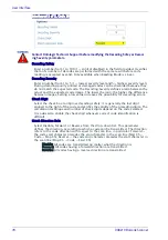
Serial Start/Stop String (max.32 chars)
Available only for Online/Serial/Network options. Click to activate the Text Entry
Tool and create the string text used to signal the beginning of the reading phase.
Use characters from NUL (00H) to ~ (7EH). Click Submit to save your text to the
origin window text field, or click Cancel to return to origin window without
transferring text. This is only available if Online option has been selected.
The Serial Start string must be different from the Serial Stop string and Motor ON/
OFF strings. When
ACK/NAK Protocol
or Energy Saving is enabled, the Serial Start/
Stop Strings cannot contain ACK/NAK characters.
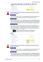
Reading Phase Timeout
Select the check box to define a timeout for the On Line Serial mode and the On
Line 1 Input mode.
Timeout (ms)
Enter a timeout in milliseconds (from 40 to 15000 ms) in the field provided. The
Timeout represents the period of time for the reading phase.
Timeout Counting From
Select Start or Stop from the drop-down list.
When Start is selected, the Timeout used to determine the reading phase will begin
from the Start Input or Serial Start String (normal operation)
Summary of Contents for DX8210
Page 1: ...DX8210 Reference Manual Omnidirectional Barcode Scanner ...
Page 31: ...Installation Reference Manual 19 Small Side Mounted L Bracket Options ...
Page 45: ...Tachometer Wiring to CBX510 Reference Manual 33 ...
Page 47: ...Tachometer Wiring to CBX510 Reference Manual 35 ...
Page 49: ...Digital Output Configuration to CBX510 Reference Manual 37 Unpowered Outputs Powered Outputs ...
Page 268: ...Barcode Scanning Features 256 DX8210 Barcode Scanner DX8210 2100 0 25 mm 10mil ...
Page 269: ...Reading Diagrams Reference Manual 257 DX8210 2100 0 30 mm 12mil ...
Page 270: ...Barcode Scanning Features 258 DX8210 Barcode Scanner DX8210 2100 0 38 mm 15mil ...
Page 271: ...Reading Diagrams Reference Manual 259 DX8210 2100 0 50 mm 20 mil ...
Page 272: ...Barcode Scanning Features 260 DX8210 Barcode Scanner DX8210 4100 0 38 mm 15 mil ...
Page 273: ...Reading Diagrams Reference Manual 261 DX8210 4100 0 50 mm 20 mil ...
Page 274: ...Barcode Scanning Features 262 DX8210 Barcode Scanner DX8210 4200 0 25 mm 10 mil ...
Page 275: ...Reading Diagrams Reference Manual 263 DX8210 4200 0 30 mm 12 mil ...
Page 297: ...Reference Manual 285 ...
Page 298: ......
Page 299: ......


