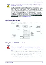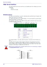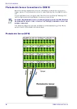
CBX510 Connection Box
Reference Manual
27
The CBX connection boxes provide flexible connectivity to a range of I/O devices
as well as serial hosting. The DX8210 connects to the CBX via its I/O port using a
single 17-pin M12 to 25-pin D cable. The CBX connection box also provides
space for an optional BM100 backup module (recommended) for parameter stor-
age, allowing quick replacement and configuration of the scanners.
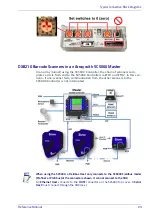
In a system with multiple scanners and other devices required in a scanning
array (tunnel), an SC5000 Controller serves as the system Master and provides
communications between devices and to the Host. Complete installation infor-
mation for the SC5000 Controller is available in the
SC5000 System Controller
Reference Manual
CBX510 Connection Box
Complete installation information for the connection box is available in the
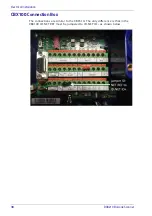
CBX510 Installation Manual available at www.datalogic.com. A simple drawing of
the interior of the box is shown below.
Wiring Into the CBX510 Connection Box
Loose-lead cables must pass through the water-tight seals in the base of the
CBX510 connection box. Insert the cables allowing enough slack for the individ-
ual wires to reach the appropriate pin block connectors. Securely tighten the
water-tight seals after the cables have been inserted.
Insulation on individual wires should be removed to expose 13 mm [0.5 inch] of
bare metal before inserting into the pin block.
Ground the scanner to safety ground (protective earth ground (PE)). See wiring recom-
mendations for safety ground.
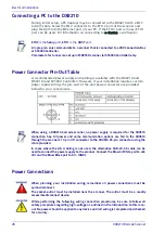
DO NOT
connect a separate power source to the CBX510 connection box. The CBX510
receives its power through its connection to the DX8210/DX8210 Barcode Scanner.
Connecting a separate power source will be detrimental to the system operation.
DISCONNECT POWER
from the scanning system and CBX510 before wiring any compo-
nents.
Summary of Contents for DX8210
Page 1: ...DX8210 Reference Manual Omnidirectional Barcode Scanner ...
Page 31: ...Installation Reference Manual 19 Small Side Mounted L Bracket Options ...
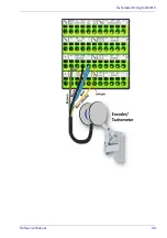
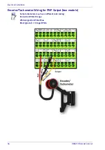
Page 45: ...Tachometer Wiring to CBX510 Reference Manual 33 ...
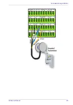
Page 47: ...Tachometer Wiring to CBX510 Reference Manual 35 ...
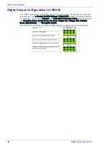
Page 49: ...Digital Output Configuration to CBX510 Reference Manual 37 Unpowered Outputs Powered Outputs ...
Page 268: ...Barcode Scanning Features 256 DX8210 Barcode Scanner DX8210 2100 0 25 mm 10mil ...
Page 269: ...Reading Diagrams Reference Manual 257 DX8210 2100 0 30 mm 12mil ...
Page 270: ...Barcode Scanning Features 258 DX8210 Barcode Scanner DX8210 2100 0 38 mm 15mil ...
Page 271: ...Reading Diagrams Reference Manual 259 DX8210 2100 0 50 mm 20 mil ...
Page 272: ...Barcode Scanning Features 260 DX8210 Barcode Scanner DX8210 4100 0 38 mm 15 mil ...
Page 273: ...Reading Diagrams Reference Manual 261 DX8210 4100 0 50 mm 20 mil ...
Page 274: ...Barcode Scanning Features 262 DX8210 Barcode Scanner DX8210 4200 0 25 mm 10 mil ...
Page 275: ...Reading Diagrams Reference Manual 263 DX8210 4200 0 30 mm 12 mil ...
Page 297: ...Reference Manual 285 ...
Page 298: ......
Page 299: ......

