


Messaging | Protocol Index
Reference Manual
145
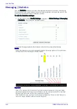
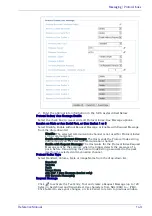
Example:
Referring to the window image above, if the read code is SDFR1235689123ASER
the transmitted code (depending on the selected Pattern Mode) will be:
Keep Before: SDFR
Keep After: 5689123ASER
Keep Middle: 5689
No Index/Message Received
Select one of the following options from the drop-down:
Use Repeated Character
Use Specified Message
No Index/Message – User Message or Repeated Character
Click
to activate the Text Entry Tool and create a No Index User Message or
Repeated Character. Click Submit to save your changes, or Cancel to the previous
window.
Distance from Message Receipt to Trigger
Enter the distance of travel between when a package hits the trigger (presence
sensor) to when it should receive an expected message from, for example, a scale
or other device.
When the Receive on Main Serial Port parameter of the selected interface port is set
to Enable without Request Message, this parameter specifies the distance from the
Trigger Line (i.e. Presence Sensor) to the expected receiving point of the Protocol
Index/Aux Message. If set to 0 the Protocol Index/Aux Message must arrive during
the active reading phase otherwise it will be discarded.
Socket Settings
If ASI ADP/Mux message is selected for Protocol Index Type, the following options
are available.
ASI Device Type
Select AV6010 or AXIOM/AL5010 from the drop-down
ASI Device Transmit Edge
Select Leading or Trailing from the drop-down.
ASI Device Transmit Point
Enter the transmit point in inches or mm.
Receive on Profibus/ Profinet
Select Disable, Enable with Request, or Enable without Request from the drop-
down. This option is only available with the Profibus or Profinet SC5000 unit.
3. When you have finished making changes, click Update All to save all pend-
ing changes, click Reset All to revert to all previously saved values, and click
Reset Page to revert to previous saved values on the current page.
Summary of Contents for DX8210
Page 1: ...DX8210 Reference Manual Omnidirectional Barcode Scanner ...
Page 31: ...Installation Reference Manual 19 Small Side Mounted L Bracket Options ...
Page 45: ...Tachometer Wiring to CBX510 Reference Manual 33 ...
Page 47: ...Tachometer Wiring to CBX510 Reference Manual 35 ...
Page 49: ...Digital Output Configuration to CBX510 Reference Manual 37 Unpowered Outputs Powered Outputs ...
Page 268: ...Barcode Scanning Features 256 DX8210 Barcode Scanner DX8210 2100 0 25 mm 10mil ...
Page 269: ...Reading Diagrams Reference Manual 257 DX8210 2100 0 30 mm 12mil ...
Page 270: ...Barcode Scanning Features 258 DX8210 Barcode Scanner DX8210 2100 0 38 mm 15mil ...
Page 271: ...Reading Diagrams Reference Manual 259 DX8210 2100 0 50 mm 20 mil ...
Page 272: ...Barcode Scanning Features 260 DX8210 Barcode Scanner DX8210 4100 0 38 mm 15 mil ...
Page 273: ...Reading Diagrams Reference Manual 261 DX8210 4100 0 50 mm 20 mil ...
Page 274: ...Barcode Scanning Features 262 DX8210 Barcode Scanner DX8210 4200 0 25 mm 10 mil ...
Page 275: ...Reading Diagrams Reference Manual 263 DX8210 4200 0 30 mm 12 mil ...
Page 297: ...Reference Manual 285 ...
Page 298: ......
Page 299: ......


