


3.7 Software
The software for the ISD 510 servo system comprises:
•
The firmware of the VLT
®
Integrated Servo Drive
ISD
®
510 that is already installed on the device
and provides the functionality described in
.
•
The firmware of the VLT
®
Servo Access Box that is
already installed on the device.
•
A package of PLC libraries for Automation
Studio
™
for operating the ISD 510 devices (see
chapter 6.4.1 Programming with Automation
Studio
for further information).
•
A PLC library for TwinCAT
®
2 for operating the
ISD 510 devices (see
for further information).
•
ISD Toolbox: A Danfoss PC-based software tool for
commissioning and debugging the devices (see
for further information).
3.8 Fieldbus
The ISD 510 servo system has an open system architecture
realized by fast Ethernet (100BASE-T) based communi-
cation. The system supports both EtherCAT
®
and Ethernet
POWERLINK
®
fieldbuses. See the
VLT
®
Integrated Servo Drive
ISD
®
510 System Programming Guide
for further information.
In productive environments, communication to the devices
always takes place via a PLC that acts as a master. The
servo drives and the SABs can be controlled by these
communication methods:
•
Using the ISD library (available for TwinCAT
®
and
Automation Studio
™
).
•
Using the NC axis functionality of TwinCAT
®
.
•
Using the CANopen
®
CiA DS 402 standard by
reading and writing to objects.
The servo drives and the SABs can be operated with the
following cycle times (for both fieldbuses):
•
400
µ
s and multiples of it (for example, 800
µ
s,
1200
µ
s, and so on).
•
500
µ
s and multiples of it (for example, 500
µ
s,
1 ms, and so on).
When the cycle time is a multiple of 400
µ
s and 500
µ
s,
the time base of 500
µ
s is used.
The servo drive and the SAB are certified for both
fieldbuses according to the corresponding rules and
regulations. The servo drive conforms to the CANopen
®
CiA DS 402 Drive Profile.
3.8.1 EtherCAT
®
The servo drive and the SAB support the following
EtherCAT
®
protocols:
•
CANopen over EtherCAT
®
(CoE)
•
File Access over EtherCAT
®
(FoE)
•
Ethernet over EtherCAT
®
(EoE)
The servo drive and the SAB support distributed clocks. To
compensate for the failure of a communication cable
section in the system, cable redundancy is available for
both fieldbuses. See the
VLT
®
Integrated Servo Drive
ISD
®
510 System Design Guide
for further information.
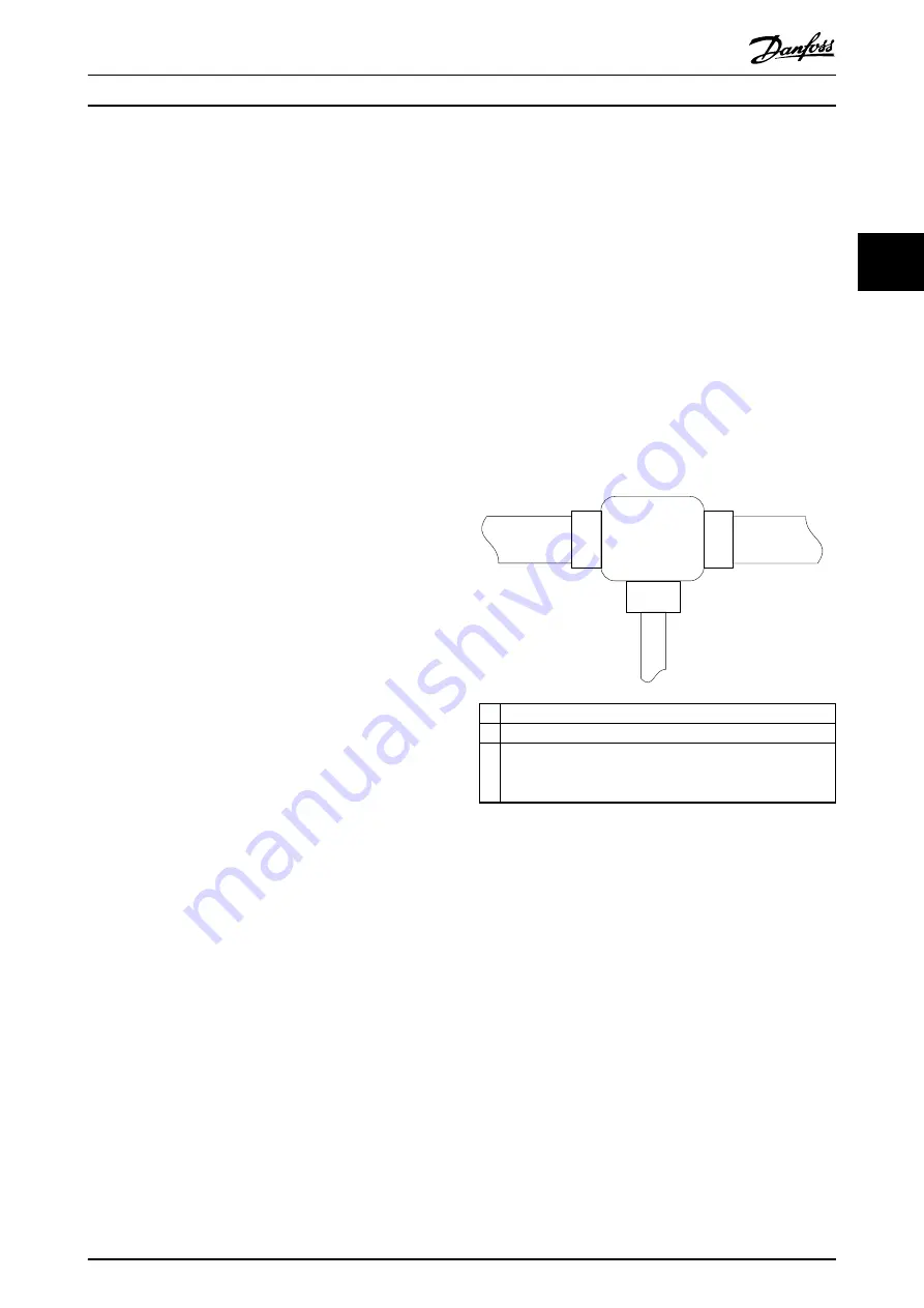
The EtherCAT
®
port assignment for the servo drive and
SAB are shown in
and
EtherCAT
Slave Controller
(ESC)
OUT
Port 1 (B)
O
U
T
Po
rt
2
(C
)
IN
Po
rt
0
(A
)
X2
X1
X3
130BE695.10
X1 M23 hybrid cable connector to SAB or previous servo drive.
X2 M23 hybrid cable connector to the next servo drive.
X3 M8 Ethernet cable connector to other EtherCAT
®
slaves, for
example EtherCAT
®
encoder.
The connector is only available on the advanced servo drive.
Illustration 3.15 EtherCAT
®
Port Assignment for the Servo
Drive
System Description
Operating Instructions
MG75K102
Danfoss A/S © 12/2015 All rights reserved.
27
3
3


