


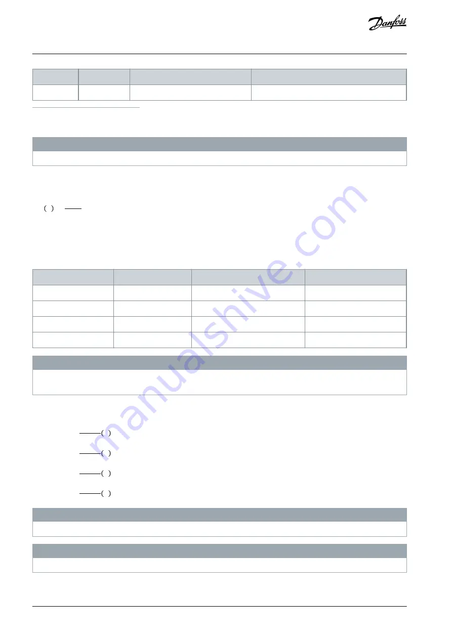
Cycle time (s)
Braking duty cycle at 100% torque
Braking duty cycle at overtorque (150/160%)
P630–P1M0
600
40%
10%
1
500 kW at 86% braking torque/560 kW at 76% brake power.
2
500 kW at 130% braking torque/560 kW at 115% brake power.
N O T I C E
Ensure that the resistor is designed to handle the required braking time.
The maximum allowed load on the brake resistor is stated as a peak power at a given intermittent duty cycle and can be calculated
as:
R
br
Ω =
Udc
2
Ppeak
where
P
peak
=P
motor
x M
br
[%]xη
motor
xη
VLT
[W]
The brake resistance depends on the DC-link voltage (U
dc)
.
Table 88: DC-link Voltage (UDC), FC 202
Size [V]
Brake active [V DC]
High-voltage warning [V DC]
Overvoltage alarm [V DC]
FC 202, 3x200–240 V
390
405
410
FC 202, 3x380–480 V
778
810
820
FC 202, 3x525–600 V
943
965
975
FC 202, 3x525–690 V
1099
1109
1130
N O T I C E
For use of 3
rd
party brake resistors, make sure to comply with the table above. The VLT® Brake Resistor MCE 101 series is optimized
for Danfoss VLT® series drives.
Danfoss recommends a brake resistance R
rec
that can guarantee that the drive can brake at the highest brake power (M
br(%)
) of
150%. The formula can be written as:
200 V: Rrec =
107780
Pmotor
Ω
500 V: Rrec =
464923
Pmotor
Ω
600 V: Rrec =
630137
Pmotor
Ω
690 V: Rrec =
832664
Pmotor
Ω
N O T I C E
The brake resistor circuit resistance selected should not be lower than what Danfoss recommends respecting the current limits.
N O T I C E
If a higher value is selected, the brake energy is reduced accordingly to a value below 150%.
AJ300847815559en-000101 / 130R0337
140 | Danfoss A/S © 2020.09
Electrical Installation
Considerations
VLT® AQUA Drive FC 202
Design Guide