


10.5 Control Wiring and Terminals
10.5.1 Shielded Control Cables
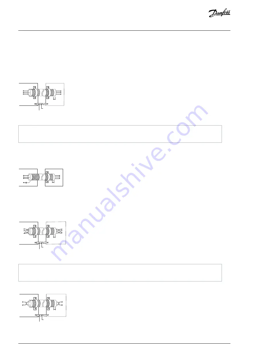
Usually, the preferred method is to secure control and serial communication cables with shielding clamps provided at both ends to
ensure the best possible high frequency cable contact.
If the ground potential between the drive and the PLC is different, electric noise could disturb the entire system. Solve this problem
by fitting an equalizing cable as close as possible to the control cable. Minimum cable cross-section: 16 mm
2
(6 AWG).
1
2
PE
FC
PE
PLC
e3
0b
b9
22
.1
2
PE
PE
<10 mm
Illustration 64: Shielding Clamps at Both Ends
1
Minimum 16 mm
2
(6 AWG)
2
Equalizing cable
10.5.1.1 50/60 Hz Ground Loops
With long control cables, ground loops may occur. To eliminate ground loops, connect 1 end of the shield to the ground with a
100 nF capacitor (keeping leads short).
100nF
FC
PE
PE
PLC
<10 mm
e3
0b
b6
09
.1
2
Illustration 65: Connection with a 100 nF Capacitor
10.5.1.2 Avoid EMC Noise on Serial Communication
This terminal is connected to ground via an internal RC link. Use twisted-pair cables to reduce interference between conductors. The
recommended method is shown in the following illustration.
PE
FC
PE
FC
e3
0b
b9
23
.1
2
PE
PE
69
68
61
69
68
61
1
2
<10 mm
Illustration 66: Twisted-pair Cables
1
Minimum 16 mm
2
(6 AWG)
2
Equalizing cable
Alternatively, the connection to terminal 61 can be omitted.
PE
FC
PE
FC
e
3
0
b
b
9
2
4
.1
2
PE
PE
69
69
68
68
1
2
<10 mm
Illustration 67: Twisted-pair Cables without Terminal 61
AJ300847815559en-000101 / 130R0337
122 | Danfoss A/S © 2020.09
Electrical Installation
Considerations
VLT® AQUA Drive FC 202
Design Guide