


Design Guide | iC7 Series Air-cooled System Modules
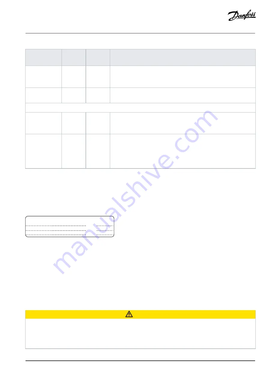
Table 39: Maintenance Schedule for Air-cooled Drives
(continued)
Component
Inspection
interval
(1)
Service
schedule
(2)
Preventive maintenance actions
Insulator gaskets
1 year
10–15
years
Inspect the insulators for signs of degradation due to high temperature and ag-
ing. Replacement is based on findings or done at the same time as DC capacitor re-
placement. Only trained service personnel are allowed to perform this action.
Batteries
1 year
7–10 years
Replace the batteries according to the manufacturer recommendation. Replace the
real-time clock battery in the control unit every 7–10 years.
Spare parts
Spare parts
1 year
2 years
Stock spares in their original boxes in a dry and clean environment. Avoid hot stor-
age areas. Electrolytic capacitors require reforming as stated in the service sched-
ule. The reforming must be performed by trained service personnel.
Exchange units
and units stored
for long periods
before commis-
sioning
1 year
2 years
Visually inspect for signs of damage, water, high humidity, corrosion, and dust
within the visual field of view without disassembly. The exchange units with
mounted electrolytic capacitors require reforming as stated in the service schedule.
The reforming must be performed by trained service personnel.
1) Defined as the time after the commissioning/startup or the time from the previous inspection.
2) Defined as the time after the commissioning/startup or the time from the previous service schedule actions.
9.2
Using the Product Modified Label
In the accessories bag, there is also a "product modified" label. The function of the label is to tell the service personnel about the changes
that are made in the AC drive.
e3
0b
g7
73
.1
0
Product modified
Date:
Date:
Date:
Figure 55: The Product Modified Label
1.
Attach the label on the side of the AC drive, in a place where it is easy to find.
a.
Attach the label, for example, next to the other labels on the power unit.
2.
If changes are made to the AC drive, write the change and date on the label.
9.3
Replacing the RTC Battery
The real-time clock (RTC) battery can be used to provide a reliable power source for the RTC. If power is lost in the control unit, the RTC
battery keeps the internal real time. The time is used for scheduled activities and timestamping occurrences based on application needs.
The RTC battery is optional and comes preinstalled if the option is selected.
CAUTION
RISK OF FIRE AND EXPLOSION
l
Replace the battery with Panasonic BR1632A (3 V, 125 °C) coin-cell battery only. Using another battery may present a risk of
fire or explosion. Only qualified personnel can exchange the battery.
l
For detailed safety information, refer to the documentation provided with the battery.
Danfoss Drives Oy © 2024.03 AJ389643111587en-000101 / 172F6361A |
75