


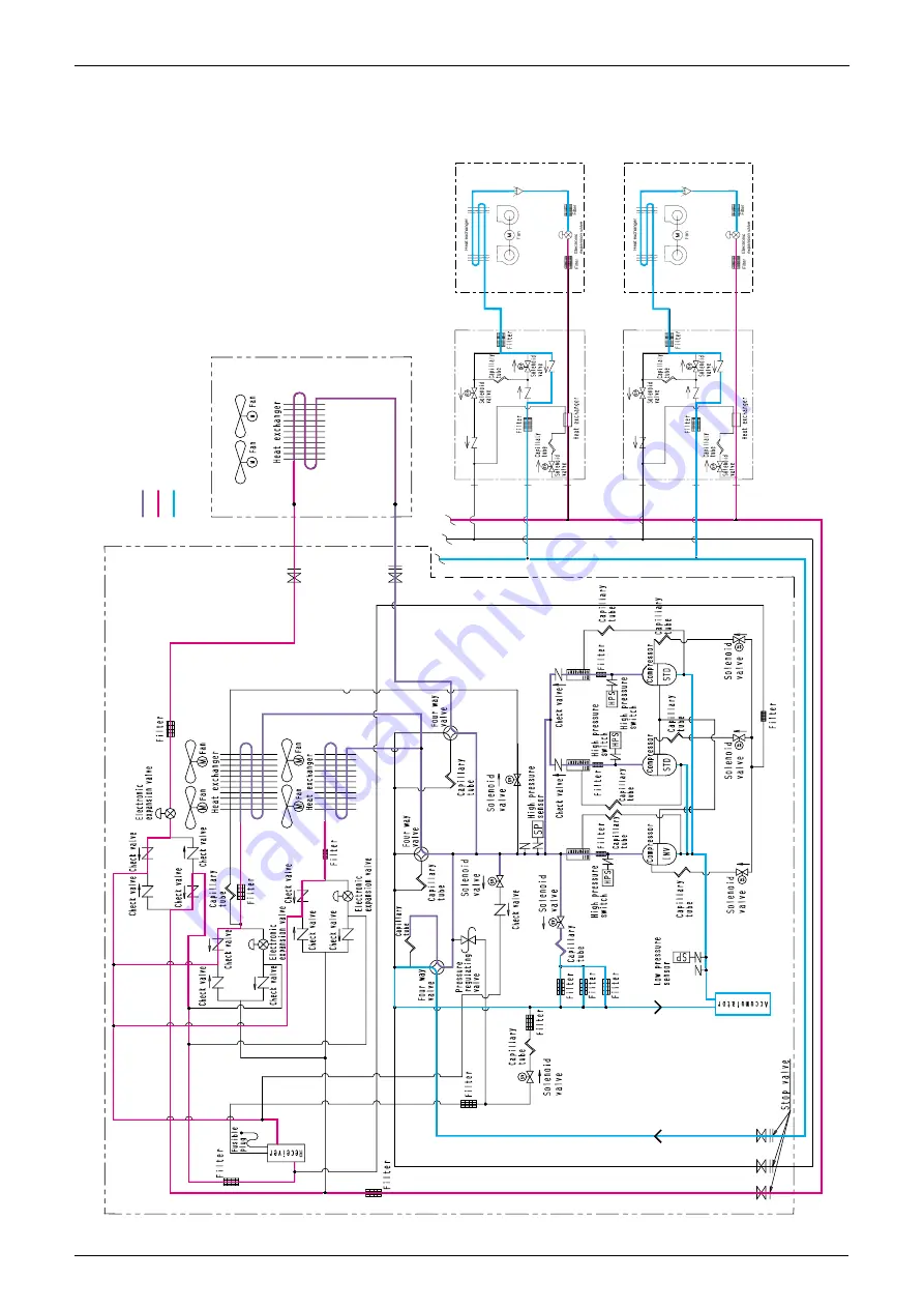
Refrigerant System Diagram
Si33-105
42
Function R407C PLUS Series Heat Recovery System
1.3.4 Oil Return Operation-Discharge (at Heating and Simultaneous
Cooling / Heating Operation or Defrost Operation)
Cooling oper
ation indoor unit
Heating oper
ation indoor unit
BS unit
BS unit
Main unit
Sub unit
He
x.3
(Y3E)
20E3
He
x.
1
20E1(Y1E)
He
x.
2
20S1(Y1R)
20S2
(R1R)
Y5S
(3D031938-5)
20E2
(Y2E)
20S3
(Y3R)
Note)
This diag
ram sho
ws a suction oper
ation, and ref
er to the outline
control f
or the details of oil retur
n and defrosting oper
ation.
High pressure & high temper
ature gas refr
iger
ant
High pressure & high temper
ature liquid refr
iger
ant
Lo
w pressure & lo
w temper
ature liquid & gas refr
iger
ant
Summary of Contents for R407C PLUS
Page 1: ...System R407C PLUS Series Heat Recovery System Si33 105 Service Manual ...
Page 11: ...Introduction Si33 105 x ...
Page 41: ...Specifications Si33 105 30 Specifications R407C PLUS Series Heat Recovery System ...
Page 147: ...Test Operation Si33 105 136 Test Operation R407C PLUS Series Heat Recovery System ...
Page 263: ...Si33 105 iv Index ...