S0709401K
Page 57
Main Control Valve (Kayaba)
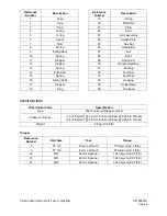
Reassembly of Overload Relief Valve
Check if there is dirt and paint chips around cap (1). Replace O-ring with new one. Clean installation
portion of relief valve and valve housing. Install relief valve and tighten cap (1). Torque: 78-88N*M
If relief valve was disassembled, adjust pressure by referring to “Over Load Relief Valve” on page 42.
NOTE:
The torque values are based on use of lubricated threads.
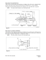
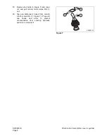
Reassembly of Low Pressure Relief Valve
Check if there is dirt and paint chips around plug (1). Replace O-ring (3) with new one. Install new O-ring
(4) on sleeve (2). Clean installation portion of relief valve and valve housing. Tighten plug (1, width across
flats: 32 mm) of relief valve. Torque: 10.50 - 11.52 kg•m (76 - 83 ft lb)
NOTE:
The torque values are based on use of lubricated threads.
Figure 55
Figure 56
Summary of Contents for Solar 300LC-V
Page 2: ......
Page 4: ......
Page 7: ...1SAFETY...
Page 8: ......
Page 46: ...S0102000 Page 38 Track Excavator Safety...
Page 47: ...1SPECIFICATIONS...
Page 48: ......
Page 54: ...S0202080K Page 6 Specifications for Solar 300LC V...
Page 70: ...S0202080K Page 22 Specifications for Solar 300LC V...
Page 71: ...1GENERAL MAINTENANCE...
Page 72: ......
Page 86: ...S0302000 Page 14 General Maintenance Procedures Return to Master Table of Contents...
Page 99: ...1UPPER STRUCTURE...
Page 100: ......
Page 102: ...S0402040K Page 2 Cab TABLE OF CONTENTS Removal 3 Installation 6...
Page 116: ...S0403050K Page 8 Counterweight Return to Master Table of Contents...
Page 140: ...S0407000 Page 6 Swing Bearing...
Page 164: ...S0408070K Page 24 Swing Reduction Gear...
Page 165: ...1LOWER STRUCTURE AND CHASSIS...
Page 166: ......
Page 190: ...S0505000 Page 24 Track Assembly 7 Tighten plug 1 Figure 48 Figure 48...
Page 191: ...S0505000 Page 25 Track Assembly TRACK SPRING AND TRACK ADJUSTING CYLINDER PARTS LIST Figure 49...
Page 193: ...1ENGINE AND DRIVE TRAIN...
Page 194: ......
Page 205: ...S0605060K Page 11 Air Conditioner Face and Defroster ARS1300L Figure 12...
Page 220: ...S0605060K Page 26 Air Conditioner...
Page 229: ...1HYDRAULICS...
Page 230: ......
Page 262: ...S0703010K Page 2 Accumulator TABLE OF CONTENTS General Description 3 Specifications 4...
Page 266: ...S0703010K Page 6 Accumulator...
Page 274: ...S0704080K Page 8 Center Joint Swivel...
Page 283: ...S0705000 Page 9 Cylinders...
Page 287: ...S0705000 Page 13 Cylinders...
Page 291: ...S0705000 Page 17 Cylinders...
Page 299: ...S0705000 Page 25 Cylinders...
Page 308: ...S0705000 Page 34 Cylinders 17 Force out pin bushing 1 from body of cylinder Figure 28...
Page 312: ...S0705000 Page 38 Cylinders...
Page 324: ...S0707270K Page 12 Swing Motor Toshiba MFC200 PARTS LIST Figure 6...
Page 355: ...S0707315K Page 11 Travel Motor with Gearbox...
Page 424: ...S0708315K Page 28 Main Pump Kawasaki CONSTRUCTION OF REGULATOR Figure 22...
Page 444: ...S0708315K Page 48 Main Pump Kawasaki...
Page 450: ...S0709401K Page 6 Main Control Valve Kayaba Figure 1...
Page 451: ...S0709401K Page 7 Main Control Valve Kayaba Figure 2...
Page 453: ...S0709401K Page 9 Main Control Valve Kayaba...
Page 455: ...S0709401K Page 11 Main Control Valve Kayaba Figure 4...
Page 467: ...S0709401K Page 23 Main Control Valve Kayaba Figure 16...
Page 500: ...S0709401K Page 56 Main Control Valve Kayaba Figure 54...
Page 552: ...S0792160K Page 6 Hydraulic Schematic S300LC V...
Page 553: ...1ELECTRICAL SYSTEM...
Page 554: ......
Page 608: ...S0802220K Page 54 Electrical System...
Page 627: ...S0802220K Page 73 Electrical System...
Page 634: ...S0892160K Page 4 Electrical Schematic S300LC V SOLAR 300LC V Figure 2...
Page 636: ...S0892160K Page 6 Electrical Schematic S300LC V...
Page 637: ...1ATTACHMENTS...
Page 638: ......
Page 658: ......


