S0102000
Page 17
Track Excavator Safety
Minimum levels of insurance coverage, work
permits or certification, physical barriers around
the work site or restricted hours of operation
may be mandated by governing authorities.
There may also be regulations, guidelines,
standards or restrictions on equipment that may
have to be followed for local requirements.
There may also be regulations related to
performing certain kinds of work. If there is any
question about whether your machine and work
site complies with the applicable standards and
regulations contact your local authorities and
agencies.
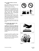
Avoid entering soft ground. It will be difficult for
the machine to escape.
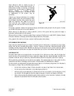
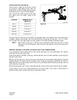
Avoid operating your machine to close to the edge of cliffs, overhangs, and deep ditches. The ground may
be weak in such areas. If the ground should collapse, the machine could fall or tip over and this could result
in serious injury or death.
Remember that the soil after heavy rain, blasting or after earthquakes, is weakened in these areas.
Earth laid on the ground and the soil near ditches is loose. It can collapse under the weight of vibration of
your machine and cause your machine to tip over.
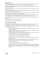
Install the head guard (FOPS) if working in areas where there is danger of falling rocks.
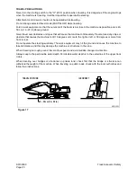
CHECKS BEFORE STARTING ENGINE
Every day before starting the engine for the first time, carry out the following checks. If these checks are
not carried out properly, there is danger of serious injury.
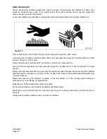
Completely remove all wood chips, leaves, grass, paper and other flammable materials accumulated in the
engine compartment and around the battery. They could cause a fire. Remove any dirt from the window
glass, mirrors, handrails, and steps.
Do not leave tools or spare parts laying around in the operator's compartment. The vibration of the
machine when traveling or during operations may cause them to fall and damage or break the control
levers or switches. They may also get caught in the gap of the control levers and cause the work equipment
to malfunction or move dangerously. This may lead to unexpected accidents.
Check the coolant level, fuel level, and hydraulic tank oil level, and check for clogged air cleaner and
damage to the electrical wiring.
Adjust the operator's seat to a position where it is easy to operate the machine, and check the seat belt and
mounts for damage and wear.
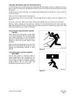
Check the operation of the gauges and the angle of the mirrors, and check that the safety lever is in
"LOCKED" position.
If any abnormalities are found in the above checks, carry out repairs immediately.
Figure 15
Summary of Contents for Solar 300LC-V
Page 2: ......
Page 4: ......
Page 7: ...1SAFETY...
Page 8: ......
Page 46: ...S0102000 Page 38 Track Excavator Safety...
Page 47: ...1SPECIFICATIONS...
Page 48: ......
Page 54: ...S0202080K Page 6 Specifications for Solar 300LC V...
Page 70: ...S0202080K Page 22 Specifications for Solar 300LC V...
Page 71: ...1GENERAL MAINTENANCE...
Page 72: ......
Page 86: ...S0302000 Page 14 General Maintenance Procedures Return to Master Table of Contents...
Page 99: ...1UPPER STRUCTURE...
Page 100: ......
Page 102: ...S0402040K Page 2 Cab TABLE OF CONTENTS Removal 3 Installation 6...
Page 116: ...S0403050K Page 8 Counterweight Return to Master Table of Contents...
Page 140: ...S0407000 Page 6 Swing Bearing...
Page 164: ...S0408070K Page 24 Swing Reduction Gear...
Page 165: ...1LOWER STRUCTURE AND CHASSIS...
Page 166: ......
Page 190: ...S0505000 Page 24 Track Assembly 7 Tighten plug 1 Figure 48 Figure 48...
Page 191: ...S0505000 Page 25 Track Assembly TRACK SPRING AND TRACK ADJUSTING CYLINDER PARTS LIST Figure 49...
Page 193: ...1ENGINE AND DRIVE TRAIN...
Page 194: ......
Page 205: ...S0605060K Page 11 Air Conditioner Face and Defroster ARS1300L Figure 12...
Page 220: ...S0605060K Page 26 Air Conditioner...
Page 229: ...1HYDRAULICS...
Page 230: ......
Page 262: ...S0703010K Page 2 Accumulator TABLE OF CONTENTS General Description 3 Specifications 4...
Page 266: ...S0703010K Page 6 Accumulator...
Page 274: ...S0704080K Page 8 Center Joint Swivel...
Page 283: ...S0705000 Page 9 Cylinders...
Page 287: ...S0705000 Page 13 Cylinders...
Page 291: ...S0705000 Page 17 Cylinders...
Page 299: ...S0705000 Page 25 Cylinders...
Page 308: ...S0705000 Page 34 Cylinders 17 Force out pin bushing 1 from body of cylinder Figure 28...
Page 312: ...S0705000 Page 38 Cylinders...
Page 324: ...S0707270K Page 12 Swing Motor Toshiba MFC200 PARTS LIST Figure 6...
Page 355: ...S0707315K Page 11 Travel Motor with Gearbox...
Page 424: ...S0708315K Page 28 Main Pump Kawasaki CONSTRUCTION OF REGULATOR Figure 22...
Page 444: ...S0708315K Page 48 Main Pump Kawasaki...
Page 450: ...S0709401K Page 6 Main Control Valve Kayaba Figure 1...
Page 451: ...S0709401K Page 7 Main Control Valve Kayaba Figure 2...
Page 453: ...S0709401K Page 9 Main Control Valve Kayaba...
Page 455: ...S0709401K Page 11 Main Control Valve Kayaba Figure 4...
Page 467: ...S0709401K Page 23 Main Control Valve Kayaba Figure 16...
Page 500: ...S0709401K Page 56 Main Control Valve Kayaba Figure 54...
Page 552: ...S0792160K Page 6 Hydraulic Schematic S300LC V...
Page 553: ...1ELECTRICAL SYSTEM...
Page 554: ......
Page 608: ...S0802220K Page 54 Electrical System...
Page 627: ...S0802220K Page 73 Electrical System...
Page 634: ...S0892160K Page 4 Electrical Schematic S300LC V SOLAR 300LC V Figure 2...
Page 636: ...S0892160K Page 6 Electrical Schematic S300LC V...
Page 637: ...1ATTACHMENTS...
Page 638: ......
Page 658: ......


