S0102000
Page 16
Track Excavator Safety
BEFORE STARTING ENGINE
WORK SITE PRECAUTIONS
Before starting operations, thoroughly check the area for any unusual conditions that could be dangerous.
Check the terrain and condition of the ground at the work site, and determine the best and safest method of
operation.
Make the ground surface as hard and horizontal as possible before carrying out operations. If there is a lot
of dust and sand on the work site, spray water before starting operations.
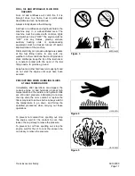
If you need to operate on a street, protect
pedestrians and cars by designating a person
for work site traffic duty or by erecting fences
and posting "No Entry" signs around the work
site.
Erect fences, post "No Entry" signs, and take
other steps to prevent people from coming close
to or entering the work site. If people come
close to a moving machine, they may be hit or
caught by the machine, and this may lead to
serious personal injury or death.
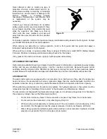
Water lines, gas lines, phone lines and high-
voltage electrical lines may be buried under the
work site. Contact each utility and identify their
locations. Be careful not to damage or cut any of
these lines.
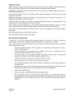
Check the condition of the river bed, and the
depth and flow of the water before operating in
water or crossing a river. NEVER be in water
that is in excess of the permissible water depth.
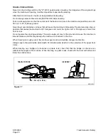
Any type of object in the vicinity of the boom
could represent a potential hazard, or cause the
operator to react suddenly and cause an
accident. Use a spotter or signal person working
near bridges, phone lines, work site scaffolds, or
other obstructions.
DANGE
R
No Entr
y
ARO1250L
Figure 13
Figure 14
Summary of Contents for Solar 300LC-V
Page 2: ......
Page 4: ......
Page 7: ...1SAFETY...
Page 8: ......
Page 46: ...S0102000 Page 38 Track Excavator Safety...
Page 47: ...1SPECIFICATIONS...
Page 48: ......
Page 54: ...S0202080K Page 6 Specifications for Solar 300LC V...
Page 70: ...S0202080K Page 22 Specifications for Solar 300LC V...
Page 71: ...1GENERAL MAINTENANCE...
Page 72: ......
Page 86: ...S0302000 Page 14 General Maintenance Procedures Return to Master Table of Contents...
Page 99: ...1UPPER STRUCTURE...
Page 100: ......
Page 102: ...S0402040K Page 2 Cab TABLE OF CONTENTS Removal 3 Installation 6...
Page 116: ...S0403050K Page 8 Counterweight Return to Master Table of Contents...
Page 140: ...S0407000 Page 6 Swing Bearing...
Page 164: ...S0408070K Page 24 Swing Reduction Gear...
Page 165: ...1LOWER STRUCTURE AND CHASSIS...
Page 166: ......
Page 190: ...S0505000 Page 24 Track Assembly 7 Tighten plug 1 Figure 48 Figure 48...
Page 191: ...S0505000 Page 25 Track Assembly TRACK SPRING AND TRACK ADJUSTING CYLINDER PARTS LIST Figure 49...
Page 193: ...1ENGINE AND DRIVE TRAIN...
Page 194: ......
Page 205: ...S0605060K Page 11 Air Conditioner Face and Defroster ARS1300L Figure 12...
Page 220: ...S0605060K Page 26 Air Conditioner...
Page 229: ...1HYDRAULICS...
Page 230: ......
Page 262: ...S0703010K Page 2 Accumulator TABLE OF CONTENTS General Description 3 Specifications 4...
Page 266: ...S0703010K Page 6 Accumulator...
Page 274: ...S0704080K Page 8 Center Joint Swivel...
Page 283: ...S0705000 Page 9 Cylinders...
Page 287: ...S0705000 Page 13 Cylinders...
Page 291: ...S0705000 Page 17 Cylinders...
Page 299: ...S0705000 Page 25 Cylinders...
Page 308: ...S0705000 Page 34 Cylinders 17 Force out pin bushing 1 from body of cylinder Figure 28...
Page 312: ...S0705000 Page 38 Cylinders...
Page 324: ...S0707270K Page 12 Swing Motor Toshiba MFC200 PARTS LIST Figure 6...
Page 355: ...S0707315K Page 11 Travel Motor with Gearbox...
Page 424: ...S0708315K Page 28 Main Pump Kawasaki CONSTRUCTION OF REGULATOR Figure 22...
Page 444: ...S0708315K Page 48 Main Pump Kawasaki...
Page 450: ...S0709401K Page 6 Main Control Valve Kayaba Figure 1...
Page 451: ...S0709401K Page 7 Main Control Valve Kayaba Figure 2...
Page 453: ...S0709401K Page 9 Main Control Valve Kayaba...
Page 455: ...S0709401K Page 11 Main Control Valve Kayaba Figure 4...
Page 467: ...S0709401K Page 23 Main Control Valve Kayaba Figure 16...
Page 500: ...S0709401K Page 56 Main Control Valve Kayaba Figure 54...
Page 552: ...S0792160K Page 6 Hydraulic Schematic S300LC V...
Page 553: ...1ELECTRICAL SYSTEM...
Page 554: ......
Page 608: ...S0802220K Page 54 Electrical System...
Page 627: ...S0802220K Page 73 Electrical System...
Page 634: ...S0892160K Page 4 Electrical Schematic S300LC V SOLAR 300LC V Figure 2...
Page 636: ...S0892160K Page 6 Electrical Schematic S300LC V...
Page 637: ...1ATTACHMENTS...
Page 638: ......
Page 658: ......


