xStack
®
DES-3810 Series Layer 3 Managed Ethernet Switch Web UI Reference Guide
172
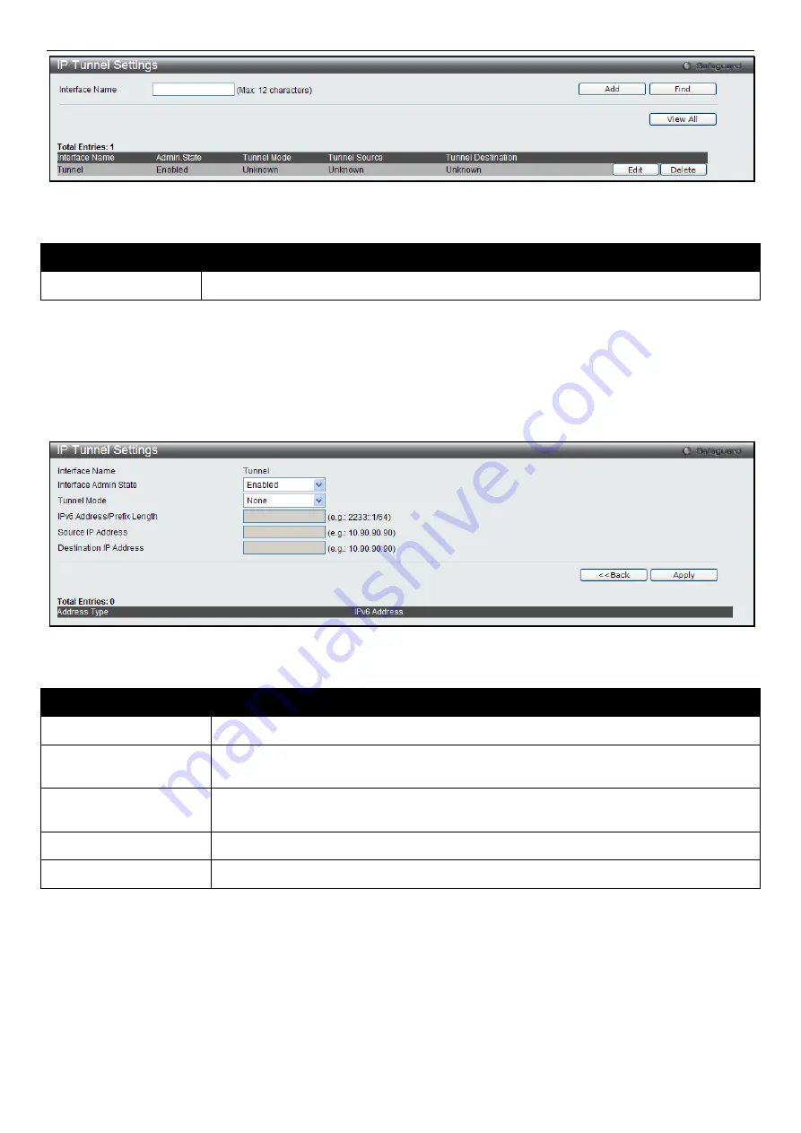
Figure 6-14 IP Tunnel Settings window
The fields that can be configured are described below:
Parameter
Description
Interface Name
Enter the IP tunnel interface name.
Click the
Add
button to add a new entry based on the information entered.
Click the
Find
button to locate a specific entry based on the information entered.
Click the
View All
button to display all the existing entries.
Click the
Edit
button to re-configure the specific entry.
Click the
Delete
button to remove the specific entry.
Click the
Edit
button to see the following window.
Figure 6-15 IP Tunnel Settings – Edit window
The fields that can be configured are described below:
Parameter
Description
Interface Admin State
Use the drop-down menu to enable or disable the interface admin state.
Tunnel Mode
Use the drop-down menu to select the tunnel modes. Available selections are
None
,
Manual
,
6to4
, and
ISATAP
.
IPv6 Address/Prefix
Length
Enter the IPv6 network address.
Source IP Address
Enter the source IP address.
Destination IP Address
Enter the destination IP address.
Click the
<<Back
button to return to the previous window.
Click the
Apply
button to accept the changes made for each individual section.
IP Tunnel GRE Settings
This window is used to configure an existing tunnel as a GRE tunnel (IPv6-in-IPv4) on the Switch. If this tunnel has
been configured in another mode before, the tunnel’s information will still exist in the database. However, whether the
tunnel’s former information is valid or not, it depends on the current mode.
To view the following window, click
L3 Features > IP Tunnel > IP Tunnel GRE Settings
, as shown below:
Summary of Contents for xStack DES-3810
Page 1: ......


