


D-Link DGS-3212SR Layer 2 Gigabit Ethernet Switch
Use the
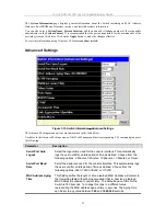
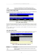
Get IP From: <Manual>
pull-down menu to choose from
BOOTP
or
DHCP
. This selects how the
switch will be assigned an IP address on the next reboot.
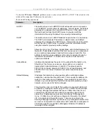
The Switch IP Settings options are:
Parameter
Description
BOOTP
The switch will send out a BOOTP broadcast request when it is powered
up. The BOOTP protocol allows IP addresses, network masks, and default
gateways to be assigned by a central BOOTP server. If this option is set,
the Switch will first look for a BOOTP server to provide it with this
information before using the default or previously entered settings.
DHCP
The switch will send out a DHCP broadcast request when it is powered up.
The DHCP protocol allows IP addresses, network masks, and default
gateways to be assigned by a DHCP server. If this option is set, the switch
will first look for a DHCP server to provide it with this information before
using the default or previously entered settings.
Manual
Allows the entry of an IP address, Subnet Mask, and a Default Gateway for
the switch. These fields should be of the form xxx.xxx.xxx.xxx, where each
xxx is a number (represented in decimal form) between 0 and 255. This
address should be a unique address on the network assigned for use by
the network administrator. The fields which require entries under this
option are as follows:
Subnet Mask
A Bitmask that determines the extent of the subnet that the Switch is on.
Should be of the form xxx.xxx.xxx.xxx, where each xxx is a number
(represented in decimal) between 0 and 255. The value should be
255.0.0.0 for a Class A network, 255.255.0.0 for a Class B network, and
255.255.255.0 for a Class C network, but custom subnet masks are
allowed.
Default Gateway
IP address that determines where packets with a destination address
outside the current subnet should be sent. This is usually the address of a
router or a host acting as an IP gateway. If your network is not part of an
intranet, or you do not want the Switch to be accessible outside your local
network, you can leave this field unchanged.
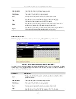
VID
This allows the entry of a VLAN ID from which a management station will
be allowed to manage the switch using TCP/IP (in-band via web manager
or Telnet). Management stations that are on VLANs other than the one
entered in the VID field will not be able to manage the switch in-band
unless their IP addresses are entered in the Security IP Management
menu. If VLANs have not yet been configured for the switch, the default
VID (1) contains all of the switch’s ports. There are no entries in the
Security IP Management table, by default, so any management station that
can connect to the switch can access the switch until either a management
VLAN (see page 38) is specified or Management Station IP Addresses
(see page 28) are assigned.
27