


D-Link DGS-3212SR Layer 2 Gigabit Ethernet Switch
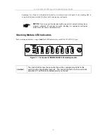
(i.e. Activity--Act) of data occurring at a port.
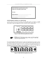
The switch includes a digital indicator (labeled
STACK NO
) to indicate the switch
status in a stacked switch group. A “0” indicates the DGS-3212SR is acting as a
standalone switch. An “F” indicates the switch is acting in the capacity of a master
switch of a stacked group of DES-3226S Layer 2 switches or DES-3326S Layer 3
switches. The remaining slave switches in the group will display a corresponding
Stack NO.
(1-C) to indicate the logical position of the slave switch in the stacked
group. See the discussion of Switch Stacking below for more information on stacking
DES-3226S/SR and DES-3326S switches.
NOTICE:
The DGS-3212SR can be used to manage a switch stack consisting of
only DES-3226S or DES-3226SR switches. The stacking of DGS-3212SR
switches is not supported at this time.
NOTICE:
At the time of the writing of this manual, stacking of multiple DGS-
3212SR switches is not supported. The
Stack NO.
LED on the switch’s front panel
will display an
F
, regardless of the switch’s stacking mode (Master switch in a
switch stack, or Standalone mode).
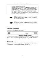
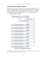
Rear Panel Description
The rear panel of the switch contains an AC power connector.
Figure 1-3. Rear panel view of the Switch
The AC power connector is a standard three-pronged connector that supports the power cord. Plug-in the female
connector of the provided power cord into this socket, and the male side of the cord into a power outlet. The
switch automatically adjusts its power setting to any supply voltage in the range from 100 ~ 240 VAC at 50 ~ 60
Hz.
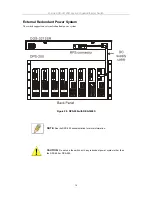
RPS Connector
Connect the optional external redundant power supply to the RPS connector. If the switch’s internal power unit
fails, the redundant power system automatically supplies power to the switch for uninterrupted operation.
The switch supports the D-Link RPS-200 or RPS-500 redundant power supply units.
3