


D-Link DGS-3212SR Layer 2 Gigabit Ethernet Switch
DGS-3212SR:4#config stacking mode enable
Command: config stacking mode enable
Success.
DGS-3212SR:4#...................................................................
................................................................................
.................................................................
DGS 3212SR 4#
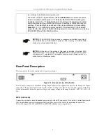
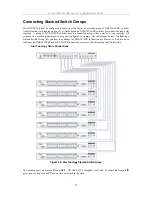
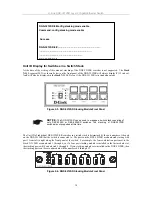
Unit ID Display for Switches in a Switch Stack
At the time of the writing of this manual, stacking of the DGS-3212SR switches is not supported. The
Stack
NO
. 8-segment LED (as shown below) on the front panel of the DGS-3212SR will always display
F
(15 in hex).
An
F
will also be displayed in the
Stack NO
. LED even if the DGS-3212SR is in standalone mode.
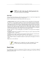
Figure 2-5. DGS-3212SR Stacking Module Front Panel
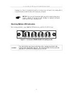
NOTICE:
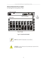
The DGS-3212SR can be used to manage a switch stack consisting of
only DES-3226S or DES-3226SR switches. The stacking of DGS-3212SR
switches is not supported at this time.
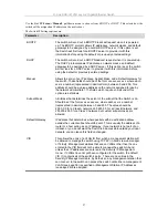
The Unit ID of individual DES-3226S/SR switches in a switch stack is determined by the port number of the port
on the DGS-3212SR that the switch is connected to. The ports on the DGS-3212SR are numbered starting with
port 1 from left to right along the front panel of the switch. For example, the four combination ports next to the
Stack NO. LED are numbered 1 through 4, so if a four port stacking module is installed in the first module slot,
the stacking ports will be numbered 5 through 8. If two stacking modules are installed in the DGS-3212SR, then
the stacking ports on the second module will be numbered 9 through 12.
Figure 2-6. DGS-3212SR Stacking Module Front Panel
14