background image

2 – 4

© 2018 Cyphre Security Solutions, LLC.

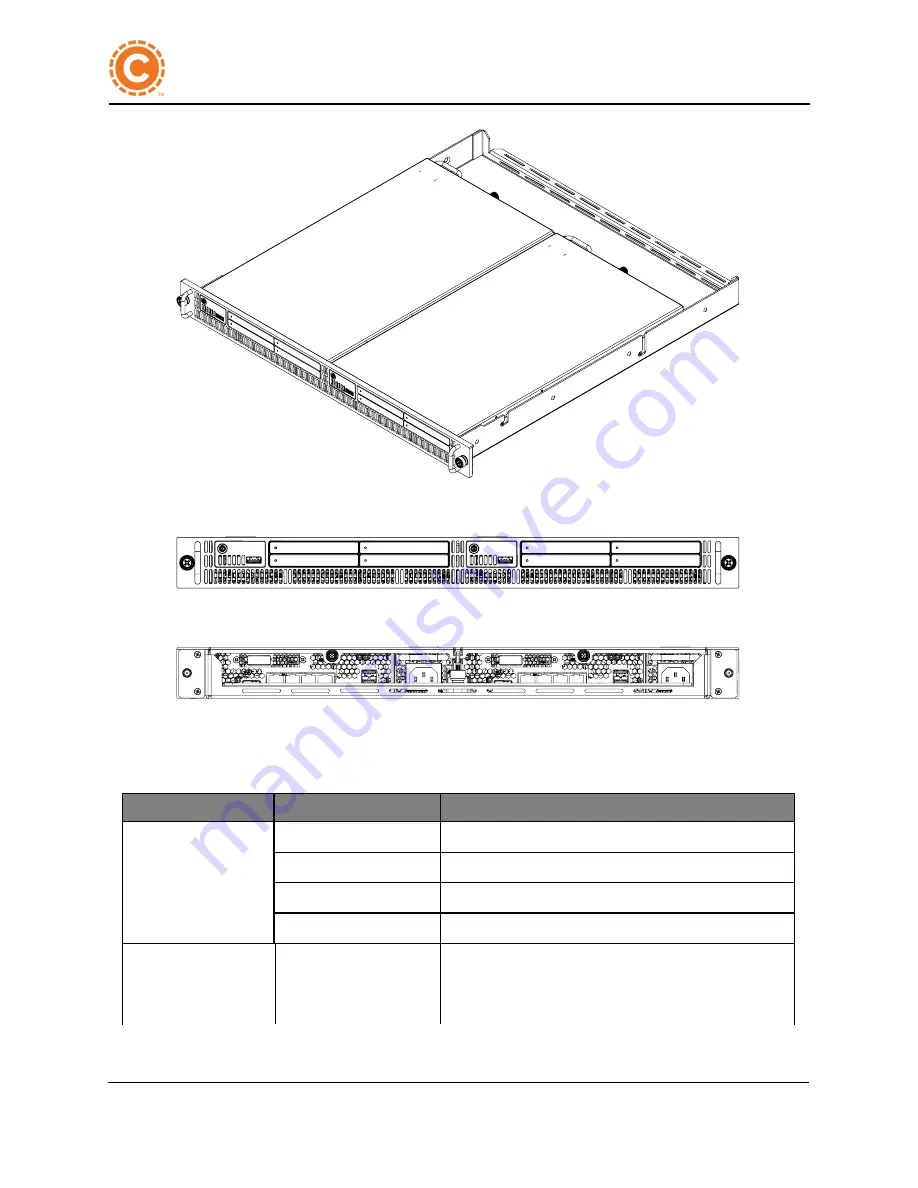
Figure 2 - 2: BT1 Security Appliance in Side-by-Side Optional Tray Accessory

Figure 2 - 3: BT1 Security Appliance Front Panel with Bezel Accessory

Figure 2 - 4: BT1 Security Appliance Rear Panel

Table 2 - 1. describes the indicators on the system front and rear panels.

LED

Color

Description

Hard drive indicators

(Qty 4. 1 Per hard

drive)

Green steady

Hard drive is quiesced

Green flashing

Hard drive has activity

Red steady

Hard drive has an error.

Red flashing

Hard drive is in RAID rebuild mode.

1 gigabit RJ45 Link

Indicators

Enet1 and Enet2

Green steady

(Left side)

The Ethernet link is up and connected to another device.

Negotiated link speed is 1 Gbps.

Table 2 - 1. Front-and Rear Panel LED Indicators

Confidential

BT1 Security Appliance User Guide

2   System Overview BT1 Security Appliance

Summary of Contents for BT1

Page 1: ...BT1 Security Appliance User Guide Company Confidential Publication Date 9 28 2018 2013 Methode Corporation ...

Page 2: ... This page intentionally left blank ...

Page 3: ...ntals 9 2 13 1 Space and Airflow Requirements 9 2 13 1 1 Adequate Airflow Example 9 2 13 2 Temperature Requirements 10 2 13 3 Power Requirements 10 2 13 3 1 Electrical Grounding Requirements 11 2 14 Hardware Components 12 2 14 1 The BT1 Security Appliance 12 2 15 Technical Specifications 24 2 16 Quick Start Guide 27 3 BT1 Installation 29 3 1 BT1 Installation Preparation 31 3 2 Prerequisite for ins...

Page 4: ...8 Hard Drive LED Indicators 73 3 19 Removing a Hard Drive from a Caddy 74 3 20 Installing a Hard Drive in Caddy 76 3 21 Power Supply Replacement 78 3 22 Fan Wall Replacement 83 3 23 Installing the Operating System 87 3 24 Operating System Installation with an External USB Device 88 3 24 1 Installation Files on the Install Media 88 3 24 2 Performing the Install 88 3 25 Operating System Network Inst...

Page 5: ... Network Boot 135 4 10 3 Boot Choices HD Installer 136 4 10 4 Boot Choices Rescue Boot 138 4 10 5 Boot Options Extra Boot Arguments 140 4 10 6 Network Configuration Machine IP 142 4 10 7 Network Configuration Server IP 144 4 10 8 Network Configuration Boot File 146 4 10 9 Network Configuration Ramdisk File 148 4 11 PCIe Tab 150 4 12 System Tab 151 4 13 RAID Tab 153 4 14 RAID Interface 154 5 About ...

Page 6: ...w netfn cmd data 183 5 19 Command sdr 184 5 20 Command sel 186 5 21 Command sensor 188 5 22 Command session 189 5 23 Command sol 190 5 24 user 192 6 Troubleshooting the BT1 193 6 1 Contacting Cyphre Customer Support 193 6 2 Symptom Information 193 6 3 Power Supply Diagnostics 195 6 4 Temperature Diagnostics 197 6 5 Ethernet 197 Index i 2018 Cyphre Security Solutions LLC iv ...

Page 7: ...ered trademark of Cyphre Security Solutions LLC CSS a RigNet subsidary BT1 Security Appliance is Copyright of Cyphre Security Solutions LLC CSS a RigNet subsidary All brand or product names other than Cyphre Security Solutions LLC CSS a RigNet subsidary or Cyphre referenced in this guide are trademarks registered trademarks or service marks of their respective holders in the United States and or o...

Page 8: ... 2018 Cyphre Security Solutions LLC vi This page intentionally left blank Confidential ...

Page 9: ...ons LLC Contacting Cyphre Security Solutions LLC Headquarters Cyphre Security Solutions LLC CSS a RigNet subsidary 15115 Park Row Suite 300 Houston Texas 77084 Phone 855 202 2005 Help Desk cyphresupport cyphre com Sales sales cyphre com Web Site www cyphre com Confidential ...

Page 10: ...Contacting Cyphre Security Solutions LLC 2018 Cyphre Security Solutions LLC viii This page intentionally left blank Confidential ...

Page 11: ... des questions ou éprouvez des difficultés contactez le service à la clientèle pour de l assistance Seul des techniciens certifiés devraient tenter d installer ou de configurer les composants Lire ce chapitre dans son intégralité avant d installer ou de configurer les composants dans le serveur BT1 Security Appliance Vous pouvez retrouver ces mises en garde sur notre site Web au www cyphre com War...

Page 12: ...le plateau BT1 ou ne pas s en servir comme une marche Installation Instructions Read the installation instructions before connecting the system to the power source Instructions d installation Lisez les instructions d installation avant de connecter le système à la source d alimentation Circuit Breaker This product relies on the facility s installation for short circuit over current protection Ensu...

Page 13: ...ation Only trained and qualified personnel should be allowed to install replace or service this equipment Installation de l équipement Seul le personnel formé et qualifié doit être autorisé à installer remplacer ou réparer cet appareil Restricted Area This unit is intended for installation in restricted access areas A restricted access area can be accessed only through the use of a special tool lo...

Page 14: ...ES USAGÉES SELON LES INSTRUCTIONS Comply with Local and National Electrical Codes Installation of the equipment must comply with local and national electrical codes Se conformer aux codes électriques locaux et nationaux L installation de l équipement doit être conforme aux codes électriques locaux et nationaux Product Disposal Disposal of this product should be handled according to all national la...

Page 15: ...tures dans l assemblage du ventilateur Power Cable When installing the product use the provided or designated connection cables and power cables Using any other cables could cause a malfunction or a fire Câble d alimentation Lors de l installation du produit utiliser des câbles de connexion fournis ou désignés et de câbles électriques L utilisation d autres câbles pourrait provoquer un dysfonction...

Page 16: ...Warning Statements Déclarations d avertissement 2018 Cyphre Security Solutions LLC xiv This page intentionally left blank Confidential ...

Page 17: ...for you if in the unlikely event a BT1 fails or operates below expected measures Review the sections below to become generally familiar with this manual It is available online in HTML5 or as PDF on http www cyphre com userguide 1 1 1 Manual Organization Contacting Cyphre You will find address and phone numbers for 2018 Cyphre Security Solutions LLC if you have questions concerning sales or technic...

Page 18: ... network and bringing the system online IPMITool The IPMITool is covered in this chapter Functionality commands and a brief history of IPMITool is included Troubleshooting This chapter covers the troubleshooting process for a BT1 Glossary List of terms abbreviations and acronyms used in this manual Confidential BT1 Security Appliance User Guide 1 About this Manual ...

Page 19: ...ppliance Chassis The single appliance configuration of the BT1 Security Appliance contains a complete standalone appliance The front panel features including power button hard disk trays and front USB connector are shown in Figure 2 5 Front Panel The rear panel contains the connectors for video Ethernet USB serial communication and AC power See Figure 2 6 BT1 Rear Panel Figure 2 1 BT1 Security App...

Page 20: ... Description Hard drive indicators Qty 4 1 Per hard drive Green steady Hard drive is quiesced Green flashing Hard drive has activity Red steady Hard drive has an error Red flashing Hard drive is in RAID rebuild mode 1 gigabit RJ45 Link Indicators Enet1 and Enet2 Green steady Left side The Ethernet link is up and connected to another device Negotiated link speed is 1 Gbps Table 2 1 Front and Rear P...

Page 21: ...d The appliance is not connected or power is not avail able Table 2 1 Front and Rear Panel LED Indicators 2 4 Connecting External Devices An array of external devices can be connected to the BT1 HDMI video USB mouse and USB keyboard standard rated devices can be connected quickly USB thumb drives and external storage devices are also fully supported When connecting external devices to your system ...

Page 22: ...ady Appliance is powered on Blue steady Power is connected and available to the system but the system is not powered on Yellow steady The appliance is currently on and is requesting a grace ful shutdown from the Operating System Red steady The appliance has experienced an error which should be investigated Not illuminated The appliance is not connected or power is not avail able Table 2 2 Front Pa...

Page 23: ...tandby connected to network Green flashing Ethernet activity is occurring Table 2 3 Rear Panel LED Indicators 2 7 Component Checklist BT1 Security Appliance ships with a main board and components already installed in the enclosure Memory and hard disks can be accessed by a properly trained support technician The system should be ready to power up and run the boot loader if your configuration custo...

Page 24: ...ur 2 5 SATA SAS SSD hard drives in front mounted easily removable drive caddies 2 11 1 RAID The BT1 Security Appliance has an LSI MegaRAID controller to support best in class RAID storage configurations RAID configuration is performed within the System Configuration Utility or using Linux based utilities The LSI MegaRAID device is an exceptionally capable SAS controller and is capable of supportin...

Page 25: ...ng normal operation the system will cycle the cooling fans RPMs creating a variable high pitched whine To prevent improper cooling and damage to the equipment do not block the ventilation openings Pour éviter un refroidissement inapproprié et une détérioration du matériel ne pas bloquer les ouvertures de ventilation To maintain proper airflow through the rack enclosure cover all gaps with blanking...

Page 26: ...he exterior of the BT1 chassis To reduce the risk of personal injury fire or damage to the appliance do not overload the AC supply circuits Consult the electrical authority about proper installation requirements for your facility Protect the apliance from power fluctuations and temporary interruptions with a regulating uninterruptible power supply This device protects the hardware from damage caus...

Page 27: ...1 Security Appliance in accordance with NFPA 70 and local and regional building codes Canadian electrical codes require you to install the equipment in accordance with Canadian Standards Association Additionally ensure all PDUs are listed or certified grounding devices Ground leakage currents associated with multiple appliances connected to a single power source can be high It is recommended that ...

Page 28: ...ty Appliances in Option Tray with Front Bezel 2 14 1 The BT1 Security Appliance The configuration of the BT1 contains the hardware of one complete appliance with the exception of the front panel bezel accessory Figure 2 9 BT1 Chassis Front Panel shows the front panel features The power button is located on the front panel The power button controls the power to the system s main board and is green ...

Page 29: ...el Description 1 Power Button Press to power up or power down 2 Hard Drive Assembly 1 3 Hard Drive Assembly 2 4 Hard Drive Assembly 3 5 Hard Drive Assembly 4 6 PEM Alignment Posts 7 Airflow intake panel 8 USB 2 0 connector for external device such as flash drive external hard drive etc 9 PEM Alignment Posts Table 2 4 BT1 Chassis Front Panel Confidential ...

Page 30: ...ow Mesh 4 HDMI connector 5 RJ 45 jacks 6 Stereo serial 1 8 inch phone jack 7 2 USB 2 0 jacks 8 Power supply AC Molex connector 9 Rear PEM alignment post 10 Front PEM alignment post 11 Power supply handle 12 Cover lock screw 13 PCIe RAID card Table 2 5 BT1 Rear Panel Components Confidential BT1 Security Appliance User Guide 2 System Overview BT1 Security Appliance ...

Page 31: ... Proprietary Power Supply 2 DIMM Slots 3 PCIe Card RAID 4 PCIe Riser Adapter Card 5 Fan Wall 6 SATA Hard Drive Connector Wall 7 Hard Drive Assembly Bays 2 and 4 8 Hard Drive Assembly Bays 1 and 3 9 High Speed 38 mm Fan 10 Power Button and USB Location 11 Hard Drive Assembly Push push Latches 12 Hard Drive Assembly Push push Latches Table 2 6 Single Chassis Top View Components Confidential ...

Page 32: ...ng Bracket Cyphre Proprietary 3 PCIe Right angle Riser Card Cyphre Proprietary 4 Internal Mini SAS 4i Connector Ports 0 3 5 External Mini SAS 4i Connector Ports 0 3 Not Used 6 Battery Connector Not Used Table 2 7 PCIe RAID Controller Card Components Confidential BT1 Security Appliance User Guide 2 System Overview BT1 Security Appliance ...

Page 33: ...Power Button and USB 3 BT1 Security Appliance HHD Bays Power Button and USB 4 Right Hand Handle and Lock Screw 5 BT1 Security Appliance Chassis Left Hand Side 6 BT1 Security Appliance Single Appliance Chassis Right Hand Side 7 Optional Tray Accessory Slide Rail mounting hole 8 Optional Tray Accessory Rear Appliance Lock Slot 9 Optional Tray Accessory 10 Optional Tray Accessory Cable Management Tab...

Page 34: ... Screw 2 Left Hand Handle 3 Right Hand Handle 4 Right Hand Lock Screw 5 Power Button and USB 2 0 Connector 6 HHD Bays x 4 7 Airflow holes 8 Power Button and USB 2 0 Connector 9 HHD Bays x 4 Table 2 9 Two BT1s in an Optional Tray Accessory Front Panel with Bezel Confidential BT1 Security Appliance User Guide 2 System Overview BT1 Security Appliance ...

Page 35: ...Add In Card Slot 6 110 V AC Molex Male Connector 7 USB 2 0 Connector x 2 8 Chassis Cover Lock Screw 9 PCIe Add In Card Slot 10 Right Hand Rack Lock Screw 11 Left hand flange handle bezel with pass through screw holes 12 HDMI Connector 13 RJ 45 Female Connectors 14 Optional Tray Accessory Cable Management 15 Chassis Rear Lock Screw 16 HDMI Connector 17 RJ 45 Female Connectors 18 Right hand flange h...

Page 36: ...PEM alignment post lock slots 4 Left hand mounting flange with lock screw and handle bezel pass through screw holes 5 Chassis brace flange 6 Chassis lock assembly pass through holes 7 Cable management rail 8 PEM alignment lock slots same on left hand side 9 Right hand slide rail pass through undercut screw holes same on left hand side Table 2 11 Optional Tray Accessory Top View Confidential BT1 Se...

Page 37: ...Appliance Figure 2 17 Optional Bezel Accessory Front View Label Description 1 Left and right hand bezel lock screw 2 Power button and USB cutouts 3 Hard drive bay cutouts 4 Airflow holes 5 Right hand handle pass through holes same on left hand side Table 2 12 Optional Bezel Accessory Front View Confidential ...

Page 38: ...ezel lock screw 2 Power button and USB cutouts 3 Hard drive bay cutouts 4 Airflow holes 5 Right hand handle pass through holes same on left hand side 6 Alignment Pins Table 2 13 Optional Bezel Accessory Rear View Figure 2 19 BT1 Power Supply Confidential BT1 Security Appliance User Guide 2 System Overview BT1 Security Appliance ...

Page 39: ...1 Security Appliance Front Rear Figure 2 20 BT1 Power Supply Front and Rear Views Label Description 1 Handle 2 AC power connector 3 Retaining screw hole 4 AC DC Indicator Lights Green OK Red Error No lights Malfunction 5 Cooling Fan 6 PCB power connectors Table 2 14 BT1 Power Supply Confidential ...

Page 40: ...m Description Architecture PC 1333 ECC DDR3 with ECC Memory module sockets Four 240 pin DIMM JEDEC RDIMMs Memory module capacities 8 GB Maximum RAM 32 GiB 8 GB x 4 Table 2 18 Memory Item Description Networking Freescale DPAA 4 Ethernet Ports 2 x 10 G Base T 2 x 1 G Base T Table 2 19 Network Item Description SATA SAS Four 2 5 inch HDD or SSD Drive bays 9 5mm Table 2 20 Hard Drives Item Description ...

Page 41: ...SB 2 0 Table 2 22 Front Panel Connectors Item Description Video type Video over USB or HDMI Table 2 23 Video Item Description Wattage 206 W Maximum Rating 100W nominal Voltage 100 240V AC 50 60 Hz auto switching Table 2 24 AC Power Supply Item Description Height 1 75 in Width 8 25 in Depth 15 25 in Form Factor 1U Weight 8 9 lbs 4 04 kg Table 2 25 Appliance Physical Dimension Item Description Opera...

Page 42: ...orage Maximum Shock tbd Operating Altitude 16 to 2 000 m 50 to 6 561 68 ft Storage Altitude 16 to 10 600 m 50 to 35 000 ft Fans Long life High efficiency Fans with Variable Auto speed Control Ultra Low Heat Output 410 BTU hr Per Appliance Table 2 26 Environmental Confidential BT1 Security Appliance User Guide 2 System Overview BT1 Security Appliance ...

Page 43: ...ory the contents in the box If anything is missing contact Customer Support 3 Place the appliance on a shelf and secure it or insert it in the optional tray accessory 4 Secure the appliance in the rack enclosure Connecting a Keyboard and Monitor The BT1 provides connection ports for an HDMI capable monitor USB keyboard and mouse if needed Connecting the Serial Console Cables Several connection opt...

Page 44: ...our version of Linux through the System Setup Utility For Rev A the BT1 supports Ubuntu Server and SUSE Linux Server Customer Support 2018 Cyphre Security Solutions LLC stands behind its product 100 Should you needs us we will be there Contact us any time Confidential BT1 Security Appliance User Guide 2 System Overview BT1 Security Appliance ...

Page 45: ... Component Checklist Lists the items in the box Tray Installing an appliance in a tray Illustrates how to install a BT1 in an optional tray accessory Power Powering Up the BT1 Provides information and cautions about powering up a BT1 the LED indicators and what to expect Memory Removing and Installing DIMMS Explains the procedures to remove and install DIMM modules Hard Drives Hard Drive Caddy Rem...

Page 46: ...rating System Network Installation Discusses installing the OS over the network RAID RAID Setup How to set up RAID RAID Controller Card Installation Discusses how to install a RAID card in the BT1 RAID Controller Card Removal Discusses how to remove a RAID card from the BT1 Ethernet Ethernet Ports Illustration of Ethernet port locations Connecting to a Network Discusses the system setup procedures...

Page 47: ...erial Cable Accessory Pack 3 2 1 Before You Begin Understand the requirements for installing the appliance into a rack Before you begin the installation process complete the following steps 1 Verify that you have received all the boxes that you ordered 2 Unpack the appliance components as needed 3 Complete a parts inventory before installing each appliance component by following these steps a Loca...

Page 48: ...ng container l BT1 l Power Up Guide l Power Cord l HDMI Male to Male Cable l 2 Ethernet Cables l 2 5 mm Phone Plug to DB9 Cable BT1Specific Pin Out l 2 5 mm Phone Plug to Phone Jack Adapter Cable BT1 Specific Pin Out l DB9 to USB FTDI Adapter Figure 3 1 Power Cord Confidential BT1 Security Appliance User Guide 3 BT1 Installation ...

Page 49: ...liance User Guide 3 BT1 Installation Figure 3 2 HDMI Male to Male Video Cable Figure 3 3 Cat 6 RJ45 Terminated Ethernet Cable Figure 3 4 2 5 mm Phone Plug to DB9 Cable BT1 Specific Pin Out CTS PPDB9 Figure 3 5 DB9 Male to USB Adapter CTS DB9FTDI Confidential ...

Page 50: ...re Security Solutions LLC Figure 3 6 HDMI Female to DVI D Male Video Adapter Figure 3 7 2 5 mm Phone Plug to Phone Jack BT1 Specific Pin Out CTS PPPJ Confidential BT1 Security Appliance User Guide 3 BT1 Installation ...

Page 51: ...LC 3 35 BT1 Security Appliance User Guide 3 BT1 Installation 3 4 Log in to the BT1 After power up and the log in prompt displays on the console enter the following case sensitive information l username svy l password jade Confidential ...

Page 52: ...iance LED Color Description Power button indicator Green steady The appliance is powered on and operational Blue steady AC power is connected and available to the system but the system is not powered on Yellow Steady Indicates the system is requesting a graceful shutdown Pressing the power button while in this state will force the system to turn off Red Steady The system is indicating that an erro...

Page 53: ...rity Solutions LLC 3 37 BT1 Security Appliance User Guide 3 BT1 Installation Figure 3 8 The BT1 Power Button on a Single Chassis Figure 3 9 The BT1 Power Buttons on Appliances in an Optional Tray Accessory Confidential ...

Page 54: ...ton should illuminate yellow then green once the power up cycle is complete OR At your console start the IPMITool and issue the appropriate commands to set the appliance IP Then issue the ipmitool chassis power on command The appliance should power on The power button should illuminate from blue to yellow to green once the power cycle is complete In an optional tray accessory installation you will...

Page 55: ...s from the appliance An Appliance may be powered down in any of the following ways From the operating system OS l On the GNU Linux command line enter shutdown h now Using the Front Panel Power Button l Press and release the power button This requests a shutdown from the OS If the OS acknowledges the request the appliance powers down OR l Press and hold the power button for 10 seconds This notifies...

Page 56: ...ial over DB9 to FTDI USB Adapter Standard Pin Out BT HDMI HDMI Male to HDMI Male Standard Pin Out Table 3 2 Console Connection Cables 3 7 1 The Basics The Cyphre supplied accessories are standard cabling options provided for your convenience However the 2 5 mm Phone Plug to DB 9 Female BT PPDB9 is specifically designed for use with the BT1 Security Appliance it uses a unique pin out You can use yo...

Page 57: ...process after 10 seconds Figure 3 11 BT1 Rear Panel 3 7 3 USB Hub For convenience you can connect a USB hub to the server s front panel USB port However you will need to connect the 2 5 mm phone plug cable to the rear of the appliance 3 7 4 Console Terminal Configuration Specifications You can use any console terminal application to connect to the BT1 The example figure below shows Tera Term on Wi...

Page 58: ...curity Solutions LLC Figure 3 13 BT1 Specific Pin Out 2 5 mm 3 Wire Phone Plug to Female DB9 Connector Cable 2 5MM Phone Jack to dB9 BT1 Specified Pin Out Confidential BT1 Security Appliance User Guide 3 BT1 Installation ...

Page 59: ...rity Appliance User Guide 3 BT1 Installation Figure 3 14 BT1 Specific Pin Out 2 5 mm 3 Wire Phone Plug to 2 5 mm Phone Jack Adapter Cable Figure 3 15 Standard Pin Out 2 5 mm 3 Wire Phone Plug to DB9 Female Connector with FTDI USB Adapter Confidential ...

Page 60: ... 44 2018 Cyphre Security Solutions LLC Figure 3 16 BT1 Specific Pin Out 2 5 mm 3 Wire Plug to DB9 Female Connector with FTDI USB Adapter Confidential BT1 Security Appliance User Guide 3 BT1 Installation ...

Page 61: ... Green Steady Left Side The Ethernet link is up and connected to another device Negotiated link speed is 1 Gbps Yellow Steady Left Side The Ethernet link is up and connected to another device Negotiated link speed is 100 Mbps or 10 Mbps Green flashing right side Ethernet activity is occurring 10 gigabit RJ45 Link Indicators Enet3 and Enet4 link Yellow steady The Ethernet link is up and connected t...

Page 62: ...net 2 eth1 1 10 100 Gb l Enet 3 eth2 10 Gb l Enet 4 eth3 10 Gb eth0 eth1 eth2 eth3 10 100 1G 10G Figure 3 18 BT1 Ethernet Ports To connect the BT1 to a network follow this procedure 1 Access the System Setup utility Requires restart and following the screen prompt 2 Navigate to the Boot screen Network Configuration Machine IP on page 142 3 Under Network Configuration select Machine IP and press En...

Page 63: ... equipment Materials Required The list of materials below are required to complete the asset installation l 2 Outer and middle slide rail assemblies L brackets pre attached l 9 10 32 x inch 2 Phillips panhead or round screws 1 spare l 9 10 32 silver cage nuts 1 spare l 3 10 32 black clip nuts 1 spare l 4 Threaded 10 32 mounting brackets not required l 1 Bag of assorted small screws not required Fi...

Page 64: ...gs The following specifications should be reviewed prior to installation l 1U telescoping in 3 sections solid bearing sliding rails l Supports system weight up to 55 lbs l Ultra thin 0 281 thick l Supports Cabinet 28 39 in depth 3 10 2 Unpacking the Tray The BT1 Optional Tray Accessory is packaged securely for safety Remove the tray from the shipping container The tray is supported in a foam lock ...

Page 65: ...User Guide 3 BT1 Installation Figure 3 21 BT1 Optional Tray Accessory in Its Secure Packaging Twist the slide rails in the foam slip lock supports so that the edges are upward as shown in the figure below Figure 3 22 Outer Slide Rails positioned Upward Confidential ...

Page 66: ...hre Security Solutions LLC Lift the slide rails from the foam locks See the image below Figure 3 23 Remove the Outer Slide Rails from the Foam Locks Confidential BT1 Security Appliance User Guide 3 BT1 Installation ...

Page 67: ...nce User Guide 3 BT1 Installation Remove the rail lock supports from the container See the figure below Figure 3 24 Removing the Foam Lock Supports Lift the tray from the packing foam front first Figure 3 25 Lifting the Tray out of the Packing Foam Confidential ...

Page 68: ...brackets are marked F or R Tip The front of the rail has a rectangular hole Figure 3 26 Outer Rail Channel Details 2 The L brackets are front to rear adjustable by loosening the black screws and sliding the L bracket Remember to re tighten the black screws See image below Figure 3 27 L bracket Adjustment 3 Adjust the rail s length to fit the outside of the rack mounting square 4 Insert 2 cage nuts...

Page 69: ...ce User Guide 3 BT1 Installation Figure 3 28 Rack Mounting Hardware Washers Screw Clip Nut and Cage Nut Figure 3 29 Outer Rail Channel Installation 1 Mount the outer channel to the rack enclosure with the supplied 10 32 x inch screws See image above Confidential ...

Page 70: ... a 2 Phillips head or slotted screwdriver Figure 3 30 Inserting the Tray into the Rack 3 10 4 Re installing the Inner Rail Slides The BT1 Optional Tray Accessory comes with the inner rail slides pre installed If you need to re install the rails follow these instructions 1 Use the 10 32 x inch flat Phillips head screws that come with the rail kit to secure the rail to the unit Four screws per rail ...

Page 71: ... 2018 Cyphre Security Solutions LLC 3 55 BT1 Security Appliance User Guide 3 BT1 Installation Figure 3 31 Location of Screws inside Tray Confidential ...

Page 72: ...ntation La prise de courant doit être installée près de l équipement et doit être facilement accessible Each appliance is fitted with PEM threaded load bearing alignment posts Each post is positioned to slip into the tray alignment slots Appliance positioned forward is locked positioned back is unlocked See images below Figure 3 32 Appliance PEM Alignment Posts Locked Figure 3 33 Appliance PEM Ali...

Page 73: ...to the tray There are PEM posts on the left and right sides Ensure they are aligned properly Figure 3 35 Installing Appliance into the Tray 2 Slide the server forward to lock the PEM posts in place See images above Figure 3 36 Moving the Appliance Forward 3 Install the appliance lock assembly as show below Confidential ...

Page 74: ...3 58 2018 Cyphre Security Solutions LLC Figure 3 37 Install Appliance Lock Assembly Confidential BT1 Security Appliance User Guide 3 BT1 Installation ...

Page 75: ...s clear no red yellow blue or green illumination See Powering Down 2 Loosen the two thumb screws on left and right hand sides of the BT1 Duo Pack Tray accessory If needed use a 2 Phillips screwdriver Figure 3 38 BT1 Optional Tray Accessory 3 Ensure the cabling in the rear has sufficient service loop to allow the tray to slide out 4 The tray is mounted on slide rails which extend the length of the ...

Page 76: ...andle on each end 8 Remove the appliance locking clamp from the rear of the tray Figure 3 39 Removing the Appliance Locking Assembly Figure 3 40 The Appliance Locking Assembly 9 Slide the appliance backward about 3 4 inch 19 05 mm Figure 3 41 Sliding the Appliance Backward 10 The appliance should lift out easily Confidential BT1 Security Appliance User Guide 3 BT1 Installation ...

Page 77: ... 2018 Cyphre Security Solutions LLC 3 61 BT1 Security Appliance User Guide 3 BT1 Installation Figure 3 42 Lifting the Appliance from the Tray Confidential ...

Page 78: ...screw is too tight to loosen by hand use a 2 Phillips screwdriver Figure 3 43 BT1 Cover Lock Screw 3 Slide the cover toward the rear about 3 4 inch to release the locking pins You can use the palm of your hand to apply gentle downward pressure to slide the cover Figure 3 44 Chassis Slide lock Slots Cover removed There are four slide lock guides on the cover two each on the right and left sides The...

Page 79: ...Security Solutions LLC 3 63 BT1 Security Appliance User Guide 3 BT1 Installation Slide lock Pins Figure 3 46 Cover Slide to Unlock 4 Lift the rear of the cover and remove Figure 3 47 Removing the Cover Confidential ...

Page 80: ...e lock slots The slide locks could bend and cause damage to the pins Note DO NOT brace the appliance by pushing against the hard drive assemblies Slide lock Pins Slide lock Slots Figure 3 50 Reinstalling the Cover To reinstall the appliance cover 1 Carefully place the cover on the appliance enclosure See Figure 3 50 Reinstalling the Cover 2 Ensure the four cover slide lock pins align two on each s...

Page 81: ...r Closed Slide lock Pins Figure 3 51 Sliding the Cover Closed Cover Flange Figure 3 52 Cover Flange 4 Ensure the cover flange slips correctly toward the front of the appliance It should slip onto the hard drive bay cross member 5 Tighten the cover screw hand tight You can add about 1 4 90 turn with a 2 Phillips screwdriver Figure 3 53 Tighten the Cover Screw Clockwise Confidential ...

Page 82: ... les meilleures pratiques ESD pour éviter une décharge électrostatique sur ou dans le serveur 1 Power down the appliance Powering Down an Appliance on page 39 2 Ensure the AC power cable is disconnected 3 Unfasten and remove the appliance from the rack 4 Remove the cover from the appliance Removing the Appliance Cover on page 62 5 Locate the DIMM slots See Figure 3 54 DIMM Slot Diagram Figure 3 54...

Page 83: ...le into its slot Pay attention to the notch along the bottom of the module to prevent inserting the DIMM incorrectly 9 Press down until it snaps into place and secure the hold down clips on each end Note Never force fit DIMMs into their sockets Ensure the notches are properly aligned 10 Power up the appliance and observe for normal operation Powering Up an Appliance on page 36 Confidential ...

Page 84: ...nnected to power The hard drive assembly is fitted with a push push latching device When you remove an assembly from its bay press gently to release the latch The assembly handle will extend See the table below Description Illustration Push push Latch Locked Push push Latch Depressed Push push Latch Released Show ing Handle Table 3 4 Push push Latch Assembly Operation Use ESD best practices to avo...

Page 85: ...eur du serveur pour installer ou supprimer des composants du système To remove a hard drive assembly from an appliance do the following 1 Press the power button to power down the appliance The appliance is powered down when the LED is blue 2 Disconnect the AC power cord The power button should NOT be illuminated 3 Disconnect all the signal cables 4 Gently press on the hard drive push push latch an...

Page 86: ...3 70 2018 Cyphre Security Solutions LLC Figure 3 57 Extracting the Hard Drive Assembly Confidential BT1 Security Appliance User Guide 3 BT1 Installation ...

Page 87: ...not be removed or installed while the appliance is connected to power The hard drive assembly is fitted with a push push latching device When you install an assembly into its bay press firmly to ensure the connector seats completely The assembly handle will extend Description Illustration Push push Latch Locked Push push Latch Depressed Push push Latch Released Show ing Handle Table 3 5 Push push ...

Page 88: ...on to power down the appliance The appliance is powered down when the LED is blue 2 Disconnect the AC power cord The power button should NOT be illuminated 3 Disconnect all the signal cables 4 Gently insert the hard drive assembly in the appropriate bay 5 Press in on the hard drive push push latch The connectors should seat 6 Release the latch it should be flush with the optional tray accessory be...

Page 89: ...sts colors and purpose 3 18 Figure 3 59 LED Indicator on hard drive push push bezel LED Color Description Hard drive indicators 4 1 Per hard drive push push latch Dark no light Hard drive quiesced or system failure Green steady Hard drive active Green flashing Hard drive activity Red steady Hard drive failure Red flashing Hard drive in RAID rebuild mode Table 3 6 Hard Drive LED Indicators Confiden...

Page 90: ...ter une décharge électrostatique sur ou dans le serveur This procedure must be performed with the appliance powered OFF and the power cord disconnected Cette procédure doit être effectuée avec le serveur hors tension et le cordon d alimentation déconnecté 1 Lay the hard drive assembly on a flat ESD protected surface Note It is important to use the proper fitting screwdriver to avoid damaging the s...

Page 91: ... 2018 Cyphre Security Solutions LLC 3 75 BT1 Security Appliance User Guide 3 BT1 Installation Figure 3 60 Removing a Hard Drive from the Caddy Confidential ...

Page 92: ...ESD pour éviter une décharge électrostatique sur ou dans le serveur This procedure must be performed with the appliance powered OFF and the power cord disconnected Cette procédure doit être effectuée avec le serveur hors tension et le cordon d alimentation déconnecté To install a hard drive into a caddy do the following 1 Place the caddy on a flat ESD protected surface 2 Ensure the 4 Philips head ...

Page 93: ...sure the hard drive screw holes line up with the caddy screw holes 6 Apply a very small amount of thread locking compound on each screw before you insert them 7 Insert and tighten each screw in the appropriate screw holes Do not over tighten Seat the screw then allow about 1 8 of a turn Confidential ...

Page 94: ...place l one screw secures the unit l convenient handle to pull supply out l precision PCB connectors l status indicator lights on top l only need to remove cover to access Figure 3 62 BT1 Power Supply Front Rear Figure 3 63 BT1 Power Supply Front and Rear Views Label Description 1 Handle Table 3 7 BT1 Power Supply Confidential BT1 Security Appliance User Guide 3 BT1 Installation ...

Page 95: ...leures pratiques ESD pour éviter une décharge électrostatique sur ou dans le serveur To replace the power supply in the BT1 1 Ensure the servers in the Duo Pack Tray are powered down 2 Ensure the appliance is powered down 3 Loosen the retaining screws on each side of the tray bezel Figure 3 64 Power Buttons on the Duo Pack Appliances 4 Slide the Duo Pack Tray out from the rack 5 Remove the applian...

Page 96: ...PEM alignment posts are in the lift out position See image below Figure 3 66 PEM Alignment posts in the lift out position 9 Lift the chassis out of the optional tray accessory 10 With a 2 Philips screwdriver unscrew the cover retaining screw Figure 3 67 Cover Retaining Screw Confidential BT1 Security Appliance User Guide 3 BT1 Installation ...

Page 97: ...e Philips screw from the side of the chassis shown in the image below Figure 3 68 Retaining Screw and Power Supply Removal 13 The power supply slides out easily Note Use care when removing the power supply Lifting the unit before the connector has been cleared could damage the connecting components 14 Insert the new power supply Ensure it slides all the way in so that the power connector seats com...

Page 98: ...rew and gently tighten with a 2 Philips screwdriver 16 Reinstall the server cover See Closing the Appliance for cover re installation 17 Reinstall the appliance into the optional tray accessory 18 Reinstall the system into the rack 19 Follow power up procedures Confidential BT1 Security Appliance User Guide 3 BT1 Installation ...

Page 99: ...s to avoid electrostatic discharge on or within the appliance Utilisez les meilleures pratiques ESD pour éviter une décharge électrostatique sur ou dans le serveur Shutdown and remove the BT1 Security Appliance 1 Ensure the appliances in the Duo Pack Tray are powered down 2 Ensure the power supplies are disconnected from the power cord 3 Loosen the retaining screws on each side of the tray bezel F...

Page 100: ...re 3 72 PEM Alignment posts in the lift out position 8 Lift the chassis out of the optional tray accessory 9 Loosen the cover retaining screw by hand or with a 2 Philips screwdriver Figure 3 73 Cover Retaining Screw 10 With the appliance chassis in a flat stable surface remove the cover by sliding it backward and lifting the rear of the cover Confidential BT1 Security Appliance User Guide 3 BT1 In...

Page 101: ...w Figure 3 74 Location of the Fan Wall 2 A multi pin header connector provides power to the wall 3 Two Philip round head screws hold the assembly in place Figure 3 75 Location of Fan Wall Electrical Header Figure 3 76 Remove Fan Wall Screws 4 Unplug the connector 5 Remove carefully the two Philips screws extracting each one and laying them to the side See the image above Confidential ...

Page 102: ...3 86 2018 Cyphre Security Solutions LLC 6 The fan wall should slip out of the chassis Figure 3 77 Lifting the Fan Wall from the Chassis Confidential BT1 Security Appliance User Guide 3 BT1 Installation ...

Page 103: ...erequisites are dependent upon your choice of Linux based operating system BT1 Security Appliances have been tested with SUSE Linux The installation methods are in the System Setup utility Use the links below to go to the appropriate topics for your installation Item Category Type Description Normal Boot Boot Choices Execute Normal boot startup Network Boot Execute Network boot startup HD Installe...

Page 104: ...rom an OS vendor Ubuntu install media conforms to Cyphre system needs 3 24 2 Performing the Install You will also need a standard HDMI capable video monitor and a USB keyboard There are three USB connectors One on the front panel two others on the rear The BT1 supports USB hubs powered or not Note The recommended installation method is from a BOOTP server over your local Ethernet Note Installing t...

Page 105: ... 2018 Cyphre Security Solutions LLC 3 89 3 BT1 Installation 8 Select the media type and press Enter 9 Follow the prompts to begin the installation Confidential ...

Page 106: ...nsuming l Network and connectivity reliability l Network bandwidth consumption l Costly appliance machine is required 3 25 3 Trivial File Transfer Protocol TFTP The suggested installation method requires TFTP and setting the kernel and initrd file names in the System Setup Any one of the three network setup methods manual TFTP DHCP can be used on the target appliance TFTP is the method by which th...

Page 107: ...ct Network Boot from the Boot menu to commence this process The appliance will not seek a bootable device prior to this method Boot Choices Network Boot on page 135 PXE extends this method by allowing the system to set up the network through BOOTP BOOTP sets up the download configuration file which describes the kernel and initrd file names This is used for more robust installations such as manage...

Page 108: ...D SAS 9280 4i4e RAID controller controls four internal 6 Gb s SAS SATA ports Before you remove your RAID controller please take a few minutes to read this installation guide The RAID controller card assembly consists of four parts l PCIe RAID Card l SAS 4 Channel Cable l PCIe right angle adapter l Metal mounting bracket Use ESD best practices to avoid electrostatic discharge on or within the appli...

Page 109: ...erial number in a safe location in case you need to contact Cyphre Customer Support To remove the RAID card 1 Power down the appliance Powering Down an Appliance on page 39 2 Disconnect the power cord from the power supply 3 Disconnect the signal cables 4 Remove the cover from the appliance Removing the Appliance Cover on page 62 5 Remove the two controller mount screws from the rear panel insert ...

Page 110: ...er toward the rear of the appliance The external port must clear the rear panel insert before extracting the card Figure 3 83 Lifting the PCIe right angle adapter and Controller Card 7 When the PCIe right angle adapter card is clear of the main board socket gently move the card assembly away from the appliance Confidential BT1 Security Appliance User Guide 3 BT1 Installation ...

Page 111: ...95 BT1 Security Appliance User Guide 3 BT1 Installation Figure 3 84 Removing the Card Assembly 8 At this time you can disconnect the controller cable from the connector Press and Pull Figure 3 85 RAID SATA SAS Connection Cable Confidential ...

Page 112: ...nternal 6 Gb s SAS SATA ports Before you install your RAID controller please take a few minutes to read this quick installation guide The RAID controller card assembly consists of four parts PCIe RAID Controller Card Assembly on page 16 for details l PCIe RAID Card l SAS 4 Channel Cable l PCIe right angle adapter l Metal mounting bracket Use ESD best practices to avoid electrostatic discharge on o...

Page 113: ...below carefully Installing a Replacement Card 1 Unpack the new RAID controller in a static free environment Remove it from the antistatic bag and inspect it for damage If the RAID controller appears to be damaged contact Cyphre Customer Support 2 The card jumpers if any are preset to Cyphre manufacturing specs Do not change their configuration 3 Connect the PCIe right angle adapter to the card as ...

Page 114: ...he PCIe right angle adapter card connector edge into the PCIe slot on the main board as shown in Figure 3 91 Inserting the PCIe right angle adapter Press down gently but firmly to seat the card completely in the slot Figure 3 91 Inserting the PCIe right angle adapter 6 Secure the RAID controller to the appliance chassis with the bracket screws Confidential BT1 Security Appliance User Guide 3 BT1 I...

Page 115: ...Installation Figure 3 92 Installing the Mounting Screws 7 Reinstall the computer cover Reinstalling the Appliance Cover on page 64 8 Reconnect the power cord and signal cables 9 Power up the appliance and observe for normal operation Powering Up an Appliance on page 36 Confidential ...

Page 116: ... through one SFF 8087 x4 internal mini SAS connector BT1 supports the LSI card configuration utility Set up and configuration can be accessed through the BT1 System Setup utility You will need to restart the appliance to access system setup BT1 Console on page 40 For information about accessing and setting up the LSI RAID card see the LSI 12Gb s MegaRAID SAS Software User Guide Rev C November 2013...

Page 117: ...hese settings Improper settings can render the appliance inoperable 4 1 Entering System Setup During power up press the ESC key when the Cyphre splash screen displays See the image below The System Setup screen displays The Main tab screen is the default screen See a screen map of the System Setup screens You can also press Tab and enter sgyboot at the boot loader prompt 4 2 Editing the Setup Scre...

Page 118: ...Figure 4 1 System Setup Screen 4 3 Screen Navigation Keys Key Description left arrow key moves the cursor to the left right arrow key moves the cursor to the right up arrow key moves the cursor up one line down arrow key moves the cursor down one line enter key on the selected option opens option popup or executes the selected option L key loads the system defaults esc key closes the options pop u...

Page 119: ... keyboard and mouse l serial console remote l serial over Ethernet remote The terminal console application for telnet or serial console must support terminal emulation to display the menu The System Setup screen contains tabs which display menu screens Each screen contains commands or fields The Cyphre System Configuration screen map below illustrates the System Setup interface flow Confidential ...

Page 120: ...4 104 2018 Cyphre Security Solutions LLC Figure 4 2 Cyphre System Configuration Screen Map Confidential BT1 Security Appliance User Guide 4 System Setup ...

Page 121: ...ion To edit a non static field press the enter key when you select the field See Figure 4 3 Example System Setup Tabs A selected option is preceded by a greater than sign See Table 4 5 for more information Figure 4 3 Example System Setup Tabs Tab Description Main System Information Advanced Processor and System Configuration PCIe PCIe configuration Boot U boot and OS Boot configuration System The ...

Page 122: ...4 106 2018 Cyphre Security Solutions LLC Confidential BT1 Security Appliance User Guide 4 System Setup ...

Page 123: ...uide 4 System Setup 4 6 Exit System Setup The System Setup can be exited after your setup changes are complete by pressing the q key To exit the System Setup screen 1 While in System Setup press q 2 The boot loader screen displays Figure 4 4 Boot Loader Screen Confidential ...

Page 124: ...TFTP copies the new image from a build server The image is burned to flash and verified After verification the interface allows you to make the image valid or validation can be done automatically At startup the images are verified before loading If both images are valid the currently configured image is used If one of the images is corrupt the valid image is loaded and a warning is displayed If bo...

Page 125: ... change the Date or Time options System Clock Time on page 117 or System Clock Date on page 119 Copyright C 2012 2018 by Cyphre LLC Basic settings and information Main Advanced PCIe Boot System RAID U Boot Version U Boot 2013 01 Build Date Sep 23 2013 15 27 15 Hardware CPU P4080E 1500MHz 8 Cores Version 2 0 Core E500MC Version 2 0 Memory Type DDR3 64 bit Memory Size 16 GiB System Clock Time 16 18 ...

Page 126: ...c none Displays the processor core information Memory Type Static none Displays the type of memory and architecture size Memory Size Static none Displays the amount of memory installed in the appliance Time System Clock Edit Time Format Field Displays the current time of day set on the appli ance and allows edit Date Edit Date Format Field Displays the current date as set on the appli ance Allows ...

Page 127: ...vanced PCIe Boot System RAID U Boot The version of the Version U Boot 2013 01 firmware This together Build Date Sep 23 2013 15 27 15 with the build date helps to uniquely identify this Hardware firmware CPU P4080E 1500MHz 8 Cores Version 2 0 Core E500MC Version 2 0 Memory Type DDR3 64 bit Memory Size 16 GiB System Clock Time 16 19 12 Date Nov 20 2013 Use arrow keys to navigate and ENTER to edit Fi...

Page 128: ...nd time of Version U Boot 2013 01 the firmware This Build Date Sep 23 2013 15 27 15 together with the version helps to uniquely identify Hardware this firmware CPU P4080E 1500MHz 8 Cores Version 2 0 Core E500MC Version 2 0 Memory Type DDR3 64 bit Memory Size 16 GiB System Clock Time 16 19 24 Date Nov 20 2013 Use arrow keys to navigate and ENTER to edit Figure 4 7 System Setup Screen Build Date Ite...

Page 129: ...ion Main Advanced PCIe Boot System RAID U Boot The type speed and version Version U Boot 2013 01 of the CPU as well as how Build Date Sep 23 2013 15 27 15 many cores are present Hardware CPU P4080E 1500MHz 8 Cores Version 2 0 Core E500MC Version 2 0 Memory Type DDR3 64 bit Memory Size 16 GiB System Clock Time 16 19 38 Date Nov 20 2013 Use arrow keys to navigate and ENTER to edit Figure 4 8 System ...

Page 130: ...d information Main Advanced PCIe Boot System RAID U Boot The type and version of the Version U Boot 2013 01 core Build Date Sep 23 2013 15 27 15 Hardware CPU P4080E 1500MHz 8 Cores Version 2 0 Core E500MC Version 2 0 Memory Type DDR3 64 bit Memory Size 16 GiB System Clock Time 16 19 51 Date Nov 20 2013 Use arrow keys to navigate and ENTER to edit Figure 4 9 System Setup Screen Core Item Category T...

Page 131: ...formation Main Advanced PCIe Boot System RAID U Boot The type of memory as Version U Boot 2013 01 detected by the firmware Build Date Sep 23 2013 15 27 15 Hardware CPU P4080E 1500MHz 8 Cores Version 2 0 Core E500MC Version 2 0 Memory Type DDR3 64 bit Memory Size 16 GiB System Clock Time 16 20 02 Date Nov 20 2013 Use arrow keys to navigate and ENTER to edit Figure 4 10 System Setup Screen Memory Ty...

Page 132: ...vanced PCIe Boot System RAID U Boot Total size of RAM detected Version U Boot 2013 01 by the firmware Build Date Sep 23 2013 15 27 15 Hardware CPU P4080E 1500MHz 8 Cores Version 2 0 Core E500MC Version 2 0 Memory Type DDR3 64 bit Memory Size 16 GiB System Clock Time 16 20 14 Date Nov 20 2013 Use arrow keys to navigate and ENTER to edit Figure 4 11 System Setup Screen Memory Size Item Category Type...

Page 133: ...ens the System Clock Time popup The change the system time 1 Use the arrow keys to select the Time option 2 Press Enter 3 Press Enter again to enter edit mode 4 Use the arrow keys to select the hour minutes or seconds 5 Press Enter to save your changes OR Press ESC to abort the operation Confidential ...

Page 134: ...st operating systems Hardware expect it Press ENTER to CPU P4080E 1500MHz 8 Cores Version 2 0 edit Core E500MC Version 2 0 Memory Type DDR3 64 bit Memory Size 16 GiB System Clock Time 16 20 34 Time 33 Date Nov 20 2013 Use arrow keys to adjust HH MM SS ESC to abort ENTER to accept Figure 4 12 System Setup Screen Time Item Category Type Options Description Time System Clock Edit Set Time Set the sys...

Page 135: ...on Copyright C 2012 2018 by Cyphre LLC Basic settings and information Main Advanced PCIe Boot System RAID U Boot The date according to the Version U Boot 2013 01 hardware clock RTC This Build Date Sep 23 2013 15 27 15 is generally set to UTC as most operating systems Hardware expect it Press ENTER to CPU P4080E 1500MHz 8 Cores Version 2 0 edit Core E500MC Version 2 0 Memory Type DDR3 64 bit Memory...

Page 136: ...18 Cyphre Security Solutions LLC Item Category Type Options Description Date System Clock Edit Set Date Enter the system date mm dd yyyy format Table 4 11 System Setup Main Tab Date Confidential 4 System Setup ...

Page 137: ...ion 2 Press Enter 3 Press Enter again to enter edit mode 4 Use the arrow keys to select the appropriate option 5 Press Enter to save your changes OR Press ESC to abort the operation Copyright C 2012 2018 by Cyphre LLC Advanced settings Main Advanced PCIe Boot System RAID IO Settings Device for IO Serial Console Memory Settings Controller Interleaving None Bank Interleaving Automatic ECC On Use arr...

Page 138: ...O port for console operations Controller Inter leaving Memory Set tings Selectable None Cache line Page Bank Super bank Select the Controller Inter leaving option Bank Interleaving Selectable Automatic None CS0 CS1 CS2 CS3 CS1 CS2 and CS2 CS3 CS0 CS1 CS2 CS3 Select the Bank Interleaving option Table 4 12 System Setup Advanced Tab Confidential 4 System Setup ...

Page 139: ...4 Use the arrow keys to select the appropriate option 5 Press Enter to save your changes OR Press ESC to abort the operation Copyright C 2012 2018 by Cyphre LLC Advanced settings Main Advanced PCIe Boot System RAID IO Settings Select which device to use Device for IO Serial Console for stdout stdin This can be either the serial port Memory Settings or the video output plus Controller Interleaving ...

Page 140: ...r IO IO Settings Selectable Video Display Sets up the signal output to the HDMI port on the rear panel Serial Console Sets up the signal output to the Serial Console port on the rear panel Table 4 13 System Setup Advanced IO Settings Device for IO Serial Console Confidential 4 System Setup ...

Page 141: ...etween memory controllers Note Making changes to these settings could render the appliance inoperable To select the Controller Interleaving option 1 Use the arrow keys to select the Controller Interleaving option 2 Press Enter 3 Press Enter again to enter edit mode 4 Use the arrow keys to select the appropriate option 5 Press Enter to save your changes OR Press ESC to abort the operation Confident...

Page 142: ...form the same read write Bank Interleaving Automatic operation done in a single ECC On controller Page interleaving will switch None between memory controllers Cache line with every page line Page transfer Bank interleaving Bank will switch between memory Super bank controllers every bank transfer Super bank is similar to bank except the switch occurs in the memory coherency module Press ENTER to ...

Page 143: ...Engages both controllers to perform the same read write operation as in a single controller Page Switches between memory controllers with every page line transfer Bank Switches between memory controllers each bank transfer Super bank Is similar to bank except the switch occurs in the memory coherence module Table 4 14 System Setup Advanced Memory Settings Controller Interleaving None Confidential ...

Page 144: ...ique that may improve memory performance for some applications CS 0 3 refers to DDR3 slots on the BT1 assembly Note Making changes to these settings could render the appliance inoperable To select the Bank Interleaving option 1 Use the arrow keys to select the Bank Interleaving option 2 Press Enter 3 Press Enter again to enter edit mode 4 Use the arrow keys to select the appropriate option 5 Press...

Page 145: ... CS0 CS1 CS2 CS3 CS1 CS2 and CS2 CS3 CS0 CS1 CS2 CS3 ENTER to select ESC to cancel Figure 4 17 Advanced Memory Settings Item Category Type Options Description Bank Inter leaving Memory Set tings Selectable Automatic Allows the system to set the bank interleaving option Recom mended None Prevents bank interleaving Not recommended CS0 CS1 Pairs bank 0 and 1 CS2 CS3 Pairs bank 2 and 3 CS1 CS2 and CS2...

Page 146: ...ry Note Making changes to these settings could render the appliance inoperable To select the ECC option 1 Use the arrow keys to select the Bank Interleaving option 2 Press Enter 3 Press Enter again to enter edit mode 4 Use the arrow keys to select the appropriate option 5 Press Enter to save your changes OR Press ESC to abort the operation Confidential 4 System Setup ...

Page 147: ...s Press Device for IO Serial Console ENTER to edit Memory Settings Controller Interleaving Cache line Bank Interleaving Automatic ECC On On Off No changes made Figure 4 18 Advanced Memory Settings ECC Item Category Type Options Description ECC Memory Settings Selectable On ECC On Off ECC Off Table 4 16 System Setup Advanced Memory Settings ECC Confidential ...

Page 148: ...ons are executable Note Making changes to these settings could render the appliance inoperable To select the appropriate option 1 Use the arrow keys to select the desired option 2 Press Enter 3 Press Enter again to enter edit mode or execute 4 Use the arrow keys to select the appropriate option 5 Press Enter to save your changes OR Press ESC to abort the operation Confidential 4 System Setup ...

Page 149: ...en Boot Tab Item Category Type Description Normal Boot Boot Choices Execute Normal boot startup Network Boot Execute Network boot startup HD Installer Execute Hard drive boot startup Rescue Boot Execute Rescue boot startup Extra boot argu ments Boot Options Edit Enter delete extra arguments for the boot pro gram to include in the boot process Machine IP Network Con figurations Edit Enter the IPV4 ...

Page 150: ...n Advanced PCIe Boot System RAID Boot Choices Normal SVYBOOT Loader Normal Boot startup Press ENTER to Network Boot run HD Installer Rescue Boot Boot Options Extra boot argumentsquiet console ttyS0 115200 Network Configuration Machine IP unset Server IP unset Boot File u boot kernel img Ramdisk File u boot initrd img Use arrow keys to navigate and ENTER to edit Press L to load defaults Figure 4 20...

Page 151: ...t using TFTP This Normal Boot includes booting installers Network Boot or normal systems If you HD Installer are using NFS you can add Rescue Boot the kernel parameters to the Extra boot arguments Boot Options env Press ENTER to run Extra boot argumentsquiet console ttyS0 115200 Network Configuration Machine IP unset Server IP unset Boot File u boot kernel img Ramdisk File u boot initrd img Use ar...

Page 152: ...R Press ESC to abort the operation Copyright C 2012 2018 by Cyphre LLC Boot setup Main Advanced PCIe Boot System RAID Boot Choices Look for and boot from Normal Boot install media Press ENTER Network Boot to run HD Installer Rescue Boot Boot Options Extra boot argumentsquiet console ttyS0 115200 Network Configuration Machine IP unset Server IP unset Boot File u boot kernel img Ramdisk File u boot ...

Page 153: ...ns LLC 4 137 4 System Setup Item Category Type Options Description HD Installer Boot Choices Execute none Look for and boot from a preselected install media Table 4 20 System Setup Boot Setup Boot Choices HD Installer Confidential ...

Page 154: ...been backed up 3 Press Enter OR 4 Press ESC to abort the operation Copyright C 2012 2018 by Cyphre LLC Boot setup Main Advanced PCIe Boot System RAID Boot Choices Boot into SVYBOOT Loader Normal Boot shell for rescue Network Boot operations Press ENTER to HD Installer run Rescue Boot Boot Options Extra boot argumentsquiet console ttyS0 115200 Network Configuration Machine IP unset Server IP unset ...

Page 155: ...LC 4 139 4 System Setup Item Category Type Options Description Rescue Boot Boot Choices Execute Rescue Boot Boots into SVYBOOT Loader shell for rescue operations Table 4 21 System Setup Boot Setup Boot Choices Rescue Boot Confidential ...

Page 156: ... Copyright C 2012 2018 by Cyphre LLC Boot setup Main Advanced PCIe Boot System RAID Boot Choices List of extra arguments Normal Boot passed to the Linux kernel Network Boot when booting You may wish HD Installer to add things like Rescue Boot console ttyS0 115200 quiet or debugging options with Boot Options this variable Press ENTER Extra boot argumentsquiet console ttyS0 115200 to edit Network Co...

Page 157: ...ons LLC 4 141 4 System Setup Item Category Type Options Description Extra Boot Arguments Boot Options Edit Free Text Field Enter or remove boot arguments Table 4 22 System Setup Boot Setup Boot Options Extra Boot Edit Confidential ...

Page 158: ...as desired 5 Press Enter to save your changes OR Press ESC to abort the operation Copyright C 2012 2018 by Cyphre LLC Boot setup Main Advanced PCIe Boot System RAID Boot Choices The IP address for this Normal Boot system to use when Network Boot downloading via TFTP Press HD Installer ENTER to edit Rescue Boot Boot Options Extra boot argumentsquiet console ttyS0 115200 Network Configuration Machin...

Page 159: ... 4 143 4 System Setup Item Category Type Options Description Machine IP Network Con figuration Edit Free Text Field Enter the IPV4 address for the appliance Table 4 23 System Setup Boot Setup Network Configuration Machine IP Confidential ...

Page 160: ... OR Press ESC to abort the operation Copyright C 2012 2018 by Cyphre LLC Boot setup Main Advanced PCIe Boot System RAID Boot Choices The IP address of the TFTP Normal Boot server where files will be Network Boot downloaded from Press HD Installer ENTER to edit Rescue Boot Boot Options Extra boot argumentsquiet console ttyS0 115200 Network Configur Machine IP Server IP Server IP Boot File u boot ke...

Page 161: ...ns LLC 4 145 4 System Setup Item Category Type Options Description Server IP Network Configuration Edit Free Text Field Set the server IP for the local appli ance Table 4 24 System Setup Network Configuration Server IP Confidential ...

Page 162: ...is downloaded from the TFTP server when executing a network boot To select the Boot File option 1 Use the arrow keys to select the Boot File option 2 Press Enter 3 Press Enter again to enter edit mode 4 Enter the new boot filename for example u boot kernel 1 img 5 Press Enter to save your changes OR Press ESC to abort the operation Confidential 4 System Setup ...

Page 163: ...ot the network Press ENTER to edit Boot Options Extra boot argumentsquiet console ttyS0 115200 Network Configur Machine IP Boot File u boot kernel img Server IP Boot File u boot kernel img Ramdisk File u boot initrd img ENTER to accept changes ESC cancels editing Figure 4 27 System Setup Screen Boot File Item Category Type Options Description Boot File Network Con figuration Edit Free Text Field E...

Page 164: ...operation Copyright C 2012 2018 by Cyphre LLC Boot setup Main Advanced PCIe Boot System RAID Boot Choices This is the name of the Normal Boot ramdisk file initrd that Network Boot is downloaded from the TFTP HD Installer server when booting over Rescue Boot the network Press ENTER to edit Boot Options Extra boot argumentsquiet console ttyS0 115200 Network Configu Machine IP Ramdisk File u boot ini...

Page 165: ...tem Setup Item Category Type Options Description Ramdisk File Network Con figuration Edit Free Text Field The ramdisk file downloaded via TFTP when booting over the network Table 4 26 System Setup Network Configuration Ramdisk File Edit Confidential ...

Page 166: ...ess ESC to abort the operation Copyright C 2012 2018 by Cyphre LLC PCIe bus and device list Main Advanced PCIe Boot System RAID PCIe Bus 0 00 00 0 Processor 1957 0400 PCIe Bus 1 01 00 0 Mass storage controller 1000 0079 Use arrow keys to navigate and ENTER to edit Figure 4 29 System Setup Screen PCIe Item Category Type Description PCIe PCIe Bus 0 Static Displays the processor interconnect informat...

Page 167: ...m RAID Temperatures Zone 1 32 C Zone 2 64 C Fans Power Supply Use arrow keys to navigate and ENTER to edit Figure 4 30 System Setup Screen System Tab Item Category Type Options Description Zone 1 Temperatures Static none Displays the Zone 1 temperature The current tem perature of the Freescale CPU Zone 2 Static none Displays the Zone 2 temperature The current aver age temperature of the BT1 enclos...

Page 168: ...ocity of the power supply fan 1 volt Power Supply Static none Displays the current state of the 1 volt power channel 5 volt Static none Displays the current state of the 5 volt power channel 12 volt Static none Displays the current state of the 12 volt power chan nel Table 4 28 System Setup System Screen Confidential 4 System Setup ...

Page 169: ...8 by Cyphre LLC RAID Config Main Advanced PCIe Boot System RAID RAID Config Continues booting to Start RAID Config SVYBOOT in order to start the RAID Configuration Tool You will exit from the System Setup Press ENTER to run Use arrow keys to navigate and ENTER to edit Figure 4 31 RAID Tab Screen Item Category Type Options Description Start RAID Config RAID Config Execute Start RAID Config Exits th...

Page 170: ... further operations Copyright C 2012 2018 by Cyphre LLC Controllers and Information Main Advanced PCIe Boot System RAID Controller Info Product Name LSI MegaRAID SAS 9280 4i4e Serial Number SV23308401 PCI Address 00 03 00 00 Mfg Date 08 13 12 FW Package Build 12 12 0 0111 FW Version 2 130 353 1663 Driver Version 06 603 04 00 Host Interface PCIE Device Interface SAS 6G Use arrow keys to navigate an...

Page 171: ...al Number Serial Number of the RAID card PCI Address The PCIe address of the card Mfg Date Date of Manufacture FW Package Build Firmware package build date FW Version Firmware version number Driver Version Driver version number Host Interface Host interface type PCIe Device Inter face Device type the RAID card interfaces SAS 6G Table 4 30 System Setup Raid Interface Confidential ...

Page 172: ...4 System Setup 4 156 2018 Cyphre Security Solutions LLC This page intentionally left blank Confidential ...

Page 173: ...e interface to this BMC It features the ability to read the sensor data repository SDR and print sensor values display the contents of the System Event Log SEL print Field Replaceable Unit FRU inventory information read and set LAN configuration parameters and perform remote chassis power control It was originally written to take advantage of IPMI over LAN interfaces but is also capable of using a...

Page 174: ...ing FRU information LAN configuration sensor readings and remote chassis power control IPMI management of a local system interface requires a compatible IPMI kernel driver to be installed and configured On Linux this driver is called OpenIPMI and it is included in standard distributions On Solaris this driver is called BMC and is included in Solaris 10 Management of a remote station requires the I...

Page 175: ...ncryption algorithms E The remote server password is specified by the environment variable IPMI_PASSWORD f password_file Specifies a file containing the remote server password If this option is absent or if password_file is empty the password will default to NULL h Get basic usage help from the command line H address Remote server address can be IP address or hostname This option is required for l...

Page 176: ...default to NULL 5 3 IPMITool Security There are several security issues be considered before enabling the IPMI LAN interface A remote station has the ability to control a system s power state as well as being able to gather certain platform information To reduce vulnerability it is strongly advised that the IPMI LAN interface only be enabled in trusted environments where system security is not an ...

Page 177: ...ool c h d N v V I open command ipmitool c h v V I lan H hostname p port U username A authtype L privlvl a E P f password o oemtype O sel oem e esc_char command ipmitool c h v V I lanplus H hostname p port U username L privlvl a E P f password o oemtype O sel oem C ciphersuite K k kg_key y hex_kg_key e esc_char command Confidential ...

Page 178: ...ple ipmitool I open help Commands bmc chassis event fru lan raw sdr sel sensor sol isol userinfo channel Example ipmitool I open chassis help Commands status power identify policy restart_cause poh bootdev Example ipmitool I open chassis power help chassis power Commands status on off cycle reset diag soft See list of commands Confidential BT1 Security Appliance User Guide 5 About the IPMITool ...

Page 179: ...e defined events to MC mc Management Controller status and global enables sdr Print Sensor Data Repository entries and read ings sensor Print detailed sensor information fru Print built in FRU and scan SDR for FRU loc ators sel Print System Event Log SEL pef Configure Platform Event Filtering PEF sol Configure and connect IPMIv2 0 Serial over LAN tsol Configure and connect Tyan IPMIv1 5 Serial ove...

Page 180: ...un a PICMG ATA extended command firewall Configure Firmware Firewall shell Launch interactive IPMI shell exec Run list of commands from file set Set runtime variable for shell and exec echo Used to echo lines to stdout in scripts ekanalyzer Run FRU Ekeying analyzer using FRU files Table 5 2 Help for Commands Confidential BT1 Security Appliance User Guide 5 About the IPMITool ...

Page 181: ...t watchdog timer settings and countdown state reset Reset the watchdog timer to its most recent state and restart the countdown timer off Turn off a currently running watchdog countdown timer selftest Check on the basic health of the BMC by executing the Get Self Test results command and report the results getenables Displays a list of the currently enabled options for the BMC setenables option on...

Page 182: ...66 2018 Cyphre Security Solutions LLC System Event Logging oem0 OEM Defined option 0 oem1 OEM Defined option 1 oem2 OEM Defined option 2 Confidential BT1 Security Appliance User Guide 5 About the IPMITool ...

Page 183: ...currently used channel ipmitool I open channel info Channel 0xf info Channel Medium Type System Interface Channel Protocol Type KCS Session Support session less Active Session Count 0 Protocol Vendor ID 7154 getaccess channel number userid Configure the given userid as the default on the given channel number When the given channel is subsequently used the user is identified implicitly by the given...

Page 184: ...hannel is given it will display information about the currently used channel ipmitool channel info Channel 0xf info Channel Medium Type System Interface Channel Protocol Type KCS Session Support session less Active Session Count 0 Protocol Vendor ID 7154 Confidential BT1 Security Appliance User Guide 5 About the IPMITool ...

Page 185: ...n the given channel is subsequently used the user is identified implicitly by the given userid setaccess channel number userid callin on off ipmi on off link on off privilege level Configure user access information on the given channel for the given userid getciphers all supported ipmi sol channel Displays the list of cipher suites supported for the given application ipmi or sol on the given chann...

Page 186: ...the cause of the last system restart selftest Check on the basic health of the BMC by executing the Get Self Test results command and report the results policy Set the chassis power policy in the event of power failure list Return supported policies always on Turn on when power is restored previous Returned to previous state when power is restored always off Stay off after power is restored power ...

Page 187: ... simulating a power button press It is necessary for there to be Operating System support for ACPI and some sort of daemon watching for events for this soft power to work bootdev device clear cmos yes no options help Request the system to boot from an alternate boot device on next reboot The clear cmos option if supplied will instruct the BIOS to clear its CMOS on the next reboot Various options m...

Page 188: ...ags 6 Boot Initiator Info 7 Boot Initiator Mailbox set option value Set boot parameter Currently supported values for option are force_pxe Force PXE boot force_disk Force boot from default hard drive force_safe Force boot from default hard drive request Safe Mode force_diag Force boot from diagnostic partition force_cdrom Force boot from CD DVD force_bios Force boot into BIOS setup Confidential BT...

Page 189: ...rectable ECC Error Detected Note These pre defined events will likely not produce accurate SEL records for a particular system because they will not be correctly tied to a valid sensor number but they are sufficient to verify correct operation of the SEL file filename Event log records specified in filename will be added to the System Event Log The format of each line in the file is as follows EvM...

Page 190: ... The syntax of the commands is defined by the COMMANDS section in this manpage Each line may have an optional comment at the end of the line delimited with a symbol Example a command file with two lines sdr list get a list of sdr records sel list get a list of sel records Confidential BT1 Security Appliance User Guide 5 About the IPMITool ...

Page 191: ...d into the specified multirecord FRU entity edit fru id This command provides interactive editing of some supported records namely PICMG Carrier Activation Record fru id is the digit ID of the FRU default is 0 edit fru id field section index string This command may be used to set a field string to a new value It replaces the FRU data found at index in the specified section with the supplied string...

Page 192: ...6 2018 Cyphre Security Solutions LLC This command edits the data found in the multirecord area Support for OEM specific records is limited Confidential BT1 Security Appliance User Guide 5 About the IPMITool ...

Page 193: ...rity Solutions LLC 5 177 BT1 Security Appliance User Guide 5 About the IPMITool 5 14 i2c i2caddr read bytes write data This will allow you to execute raw I2C commands with the Master Write Read IPMI command Confidential ...

Page 194: ...PMI v1 5 Serial Over LAN mode An RMCP connection is made to the BMC the terminal is set to raw mode and user input is sent to the serial console on the remote server On exit the SOL payload mode is deactivated and the terminal is reset to its original settings Special escape sequences are provided to control the SOL session Terminate connection Z Suspend ipmitool X Suspend ipmitool but don t resto...

Page 195: ...efgw macaddr xx xx xx xx xx xx Set the default gateway MAC address bakgw ipaddr x x x x Set the backup gateway IP address bakgw macaddr xx xx xx xx xx xx Set the backup gateway MAC address password pass Set the null user password snmp community string Set the SNMP community string user Enable user access mode for userid 1 issue the user command to display information about userids for a given chan...

Page 196: ...tors are required to use a stronger cipher suite than normal users The format of privlist is as follows Each character represents a privilege level and the character position identifies the cipher suite number For example the first character represents cipher suite 1 cipher suite 0 is reserved the second represents cipher suite 2 and so on privlist must be 15 characters in length Characters used i...

Page 197: ...hannel gateway to use for alerts ack on off Set Alert Acknowledge on or off type pet oem1 oem2 Set the destination type as PET or OEM time seconds Set the ack timeout or unack retry interval retry number Set the number of alert retries stats get channel number Retrieve information about the IP connections on the specified channel The default will retrieve statistics on the first found LAN channel ...

Page 198: ...Each policy entry describes an alert destination A policy set is a collection of table entries PEF alert actions reference policy sets list This command lists the PEF table entries Each PEF entry relates a sensor event to an action When PEF is active each platform event causes the BMC to scan this table for entries matching the event and possible actions to be taken Actions are performed in priori...

Page 199: ...r Guide 5 About the IPMITool 5 18 Command raw netfn cmd data This will allow you to execute raw IPMI commands For example to query the POH counter with a raw command ipmitool v raw 0x0 0xf RAW REQ netfn 0x0 cmd 0xf data_len 0 RAW RSP 5 bytes 3c 72 0c 00 00 Confidential ...

Page 200: ...es C Processor1 Temp 98h ok 3 1 57 degrees C Processor2 Temp 99h ok 3 2 53 degrees C list elist all full compact event mcloc fru generic This command will read the Sensor Data Records SDR and extract sensor information of a given type then query each sensor and print its name reading and status If invoked as elist it will also print sensor number entity id and instance and asserted discrete states...

Page 201: ...file Dumps raw SDR data to a file This data file can then be used as a local SDR cache of the remote managed system with the S _file_ option on the ipmitool command line This can greatly improve performance over system interface or remote LAN fill sensors Create the SDR Repository for the current configuration Will perform a Clear SDR Repository command so be careful fill file filename Fill the SD...

Page 202: ...is can take a long time over the system interface count first count Displays the first count least recent entries in the SEL If count is zero all entries are displayed last count Displays the last count most recent entries in the SEL If count is zero all entries are displayed delete number Delete a single event delete SEL Record ID SEL Record ID Delete one or more SEL event records add filename ID...

Page 203: ...format This file can be fed back to the sel readraw ipmitool command for viewing readraw file Read and display SEL records from a binary file Such a file can be created using the sel writeraw ipmitool command time get Displays the SEL clock s current time set time string Sets the SEL clock Future SEL entries will use the time set by this command time string is of the form MM DD YYYY HH MM SS Note ...

Page 204: ...Non Critical lcr Lower Critical lnr Lower Non Recoverable thresh id lower lnr lcr lnc This allows you to set all lower thresholds for a sensor at the same time The sensor is specified by name and the thresholds are listed in order of Lower Non Recoverable Lower Critical and Lower Non Critical thresh id upper unc ucr unr This allows you to set all upper thresholds for a sensor at the same time The ...

Page 205: ...5 About the IPMITool 5 22 Command session info active all id 0xnnnnnnnn handle 0xnn Get information about the specified session s You may identify sessions by their id by their handle number by their active status or by using the keyword all to specify all sessions Confidential ...

Page 206: ... values are set in progress set complete set in progress commit write enabled true false force encryption true false force authentication true false privilege level user operator admin oem character accumulate level Decimal number given in 5 milliseconds increments character send threshold Decimal number retry count Decimal number 0 indicates no retries after packet is transmitted retry interval D...

Page 207: ...vated and the terminal is reset to its original settings Special escape sequences are provided to control the SOL session Terminate connection Z Suspend ipmitool X Suspend ipmitool but don t restore tty on restart B Send break Send the escape character by typing it twice Print the supported escape sequences deactivate Deactivates Serial Over LAN mode on the BMC Exiting Serial Over LAN mode should ...

Page 208: ...is cleared set to the NULL password Be careful when removing passwords from administrator level accounts disable userid Disables access to the BMC by the given userid enable userid Enables access to the BMC by the given userid priv userid privilege level channel number Set user privilege level on the specified channel If the channel is not specified the current channel will be used test userid 16 ...

Page 209: ...own the information To open a trouble ticket go to www cyphre com The information you gather below can be entered into the support app Information Type Your Observations Company Name Contact Name Account Number if applicable Address Phone Number Cyphre Model In this caseBT1 Serial Number Asset Tag IP Address of the appliance if possible Physical location of the appliance Address Colo Name GPS Coor...

Page 210: ...cle one in the next column Unusual Fan Noise Overheating LED Blink Code Power Button Color Absent or Other Than Green Can you reproduce the issue Yes No Circle one When did the issue occur Document the precise date and time the issue occurred Date Time What events preceded the failure After which steps does the issue occur On the back of this sheet list the steps start to finish Underline or highl...

Page 211: ...ing and Setting up RAID on page 100 The storage subsystem has an audible alarm in the RAID controller Unfortunately audible alarms are difficult to track down in the datacenter This is a last resort to troubleshooting an error Front panel LEDs show normal green but no Ethernet Powering Up an Appliance on page 36 If the front panel power LED indicates powered up and the system appears to be working...

Page 212: ...a streaming from the console port ensure you are connected correctly to the console port and the serial parameters are correct l 9600 baud l 8 bit and 1 parity on l no flow control l correct USB drivers for the device l correct serial port selection on utilities such as Tera Term If you cannot get the serial port console to work but you see other LED activity on the front and indicators on the RJ ...

Page 213: ...and possibly replace the fan FRU The fan FRU is available from Cyphre Customer Support If you observe other temperature errors and your fans are working properly contact Cyphre Customer Support 6 5 Ethernet Issue Description Ethernet If you are having network connectivity issues and you are having problems at the Linux level take a log and contact Cyphre Customer Support There are several subsyste...

Page 214: ...6 Troubleshooting the BT1 6 198 2018 Cyphre Security Solutions LLC This page intentionally left blank Confidential ...

Page 215: ...Rescue Boot 138 Boot Options Extra Boot Arguments 140 BOOTP 90 BT1 Overview 3 C caddy install hard drive 76 remove hard drive 74 Checklist Component 7 what s in the box 32 commands IPMITool Syntax 158 161 connectors front panel 6 25 rear panel 6 24 Console 40 D density 8 DHCP 90 E enviromentals 25 Ethernet 24 connecting to a network 46 ports 45 expansion bus 24 expansion slot 24 external devices 6...

Page 216: ...caddy 76 operating system 87 operating system BOOTP 90 operating system DHCP 90 operating system with external USB device 88 IO settings 123 IP Machine 142 Server 144 K Keystrokes for System Setup 102 L LED Indicators Front Panel 6 Power Supply 78 Rear Panel 7 Log in 35 M Machine IP 142 Main Tab 109 map screen for system setup 103 memory ECC 8 replacing DIMMS 66 technical specifications 24 Memory ...

Page 217: ... a server 39 power supply 25 power supply replacement 78 power up a server 36 power up after an outage 38 Processor 7 24 R RAID 8 configuring and setup 100 RAID Tab 153 154 rails attaching to tray 47 Ramdisk File 148 Rear Panel 6 Labels 14 S save and exit system setup 107 Server Component Checklist 32 connect to a network 46 environmental 83 install in a tray 56 power 78 reinstalling the cover 64 ...

Page 218: ... 148 Normal Boot 134 PCIe 150 RAID Config 153 Rescue Boot 138 Save and Exit 107 Screen Map 103 Temperature Fans Power 151 Time 117 U Boot Version 111 Ugrade 108 T Tabs system setup Advanced 121 123 125 128 130 Boot 132 134 136 138 140 142 144 146 148 Main 109 111 117 119 navigating 105 PCIe 150 RAID 153 154 System 151 Technical Specifications 24 enviromentals 25 expansion bus 24 expansion slot 24 ...

Page 219: ... 2018 Cyphre Security Solutions LLC Index v Index Upgrade system setup USB Devices Version 111 Upgrade system setup 108 USB Devices 88 Confidential ...

Reviews: