


MAINTENANCE WITH Q&A
Page 5-8
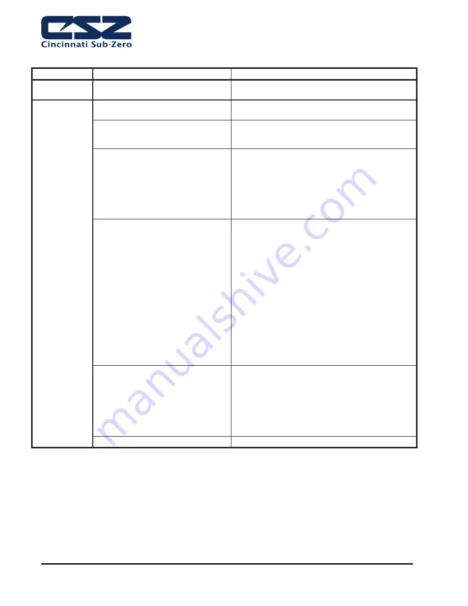
Table 6. Dry Air Purge Troubleshooting Procedures
PROBLEM
PROBABLE CAUSE
CORRECTIVE ACTION
Unit delivers
moist air
Improper operating conditions
Change temperature and RH setpoint to be within
recommended operating range for Dry Air Purge.
Moisture
indicator is pink
Solenoid core spring not seated
properly or is broken
Remove solenoid valve. Spring should be seated on
core and not broken. Replace if necessary.
Purge ori
fi
ce plugged
Remove, inspect, and clean ori
fi
ce. Use air gun to
clean. Do not force wires through critically drilled
holes.
Solenoid coil burned out
Remove cover, place iron or steel material
(screwdriver or nail) on exposed end of solenoid
base to feel the magnetic effect indicating proper
operation. Each coil should be energized for
30 seconds. Depress switch lever by hand and
listen for clicking contact. Switch should click
when depressed and when released. Replace if
necessary.
Improper cycle timer operation
Check the power supply . If the correct voltage is
not present between L1 and both of the L2 terminals,
check the wiring and protective device supplying
power to the dryer.
Dryers with DC solenoid valves should alternately
have DC voltage between L2 and DC1 and between
L2 and DC2. Replace the timer if voltage is present
at either DC terminal continuously or not at all.
Timer Input 120VAC/Timer Output 53 VDC
Timer Input 240 VAC/Timer Output 106 VDC
Timers P-06521-F1 and F2 are the standard timers
used on the HF200, HF300A and HF300B air driers.
The timers permit simultaneous switching of the
solenoid valves every 30 seconds.
Desiccant attrition or contamination
Inspect outlet air line for indication of excessive oil.
Check operation of dropout
fi
lter.
Remove chamber from manifold and depress
perforated disc at open end of chamber. If it can be
depressed more than 1/4" from the retaining ring,
replace chamber.
Water in Customer air supply lines
Find and correct problem
DRY AIR PURGE TROUBLESHOOTING PROCEDURES (OPTIONAL EQUIPMENT)
Summary of Contents for ZP 16
Page 1: ...Installation Operation Maintenance Manual ZP Series 56120 REV AH 10 2019...
Page 4: ...INTRODUCTION THIS PAGE INTENTIONALLY LEFT BLANK...
Page 6: ...CHAMBER LABELS MEANINGS THIS PAGE INTENTIONALLY LEFT BLANK...
Page 40: ...GENERAL DESCRIPTION Page 2 24 THIS PAGE INTENTIONALLY LEFT BLANK...
Page 42: ...INSTALLATION Page 3 2 Figure 1 Transporting a Chamber...
Page 46: ...INSTALLATION Page 3 6 Table 2 Water Usage SI Units...
Page 62: ...OPERATION Page 4 14 THIS PAGE INTENTIONALLY LEFT BLANK...
Page 82: ...MAINTENANCE WITH Q A Page 5 20 THIS PAGE INTENTIONALLY LEFT BLANK...
Page 84: ...SERVICE PARTS WARRANTY Page 6 2 THIS PAGE INTENTIONALLY LEFT BLANK...
Page 88: ...SYSTEM DIAGRAMS Page 9 4 THIS PAGE INTENTIONALLY LEFT BLANK...