background image

Lamp Unit Replacement

99

9.1.1 Replacing the Transparency Lamp Unit

The transparency lamp unit is located inside the scanner top cover.

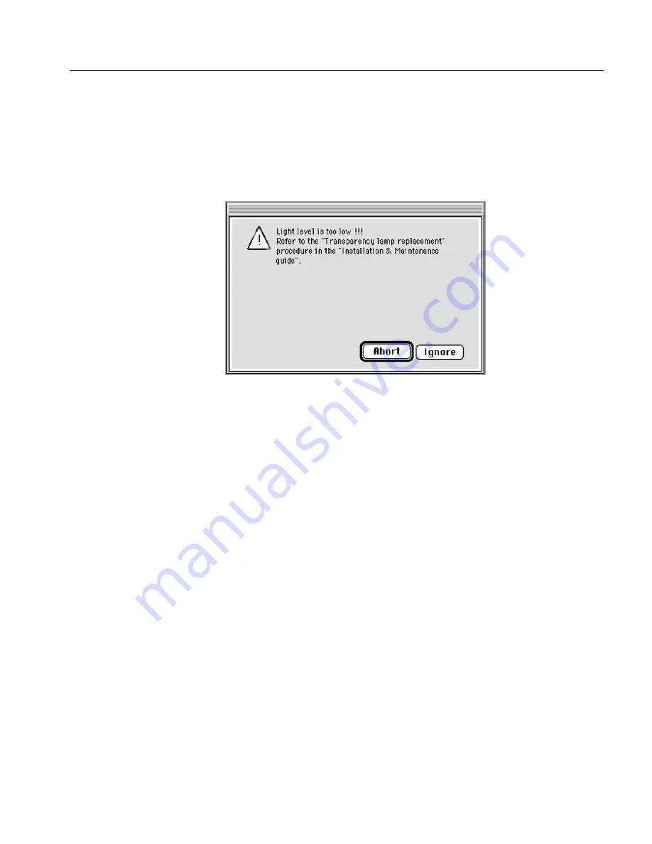
Light level is too low

The following message window is displayed on the screen.

To exit from the message window, perform one of the following:

¾

Click 

Abort

. The scanner application quits. Replace the defective 

lamp unit (see the following instructions).

¾

Click 

Ignore

 and continue with the pre-scan/scan. Replace the 

defective lamp unit when you have completed your work.

Lamp does not light up

The transparency lamps always light up a few seconds after the scanner 
is switched on.

¾

To confirm that a lamp needs replacing, switch the system 

OFF


and 

ON

 again.

If the lamp does not light up after 15 seconds, replace the lamp unit 
and try again.

Summary of Contents for iqsmar series

Page 1: ...www creo com Installation and Maintenance Guide Mac and PC Platforms English iQsmart Scanners 399Z1R946B...

Page 2: ......

Page 3: ...iQsmart Scanners Installation and Maintenance Guide Mac and PC Platforms...

Page 4: ......

Page 5: ...demarks or registered trademarks of Microsoft Corp Xerox is a registered trademark of Xerox Corp Other brand or product names are the trademarks or registered trademarks of their respective owners FCC...

Page 6: ...059 5 355 446 5 359 451 5 359 458 5 367 360 5 384 648 5 384 899 5 412 491 5 412 737 5 420 702 5 420 722 5 459 505 5 473 733 5 481 379 5 488 906 5 497 252 5 508 828 5 509 561 5 517 359 5 519 852 5 526...

Page 7: ...uired for installation 17 2 2 Unlocking Screws and Removing Packing 18 Chapter 3 FireWire Installation for PC Platform 21 3 1 FireWire Adaptor Installation 23 Chapter 4 Powering On 31 4 1 Powering on...

Page 8: ...ing for the Installation Utilities Program 76 7 12 1 Serial Number Mismatch 76 7 12 2 Serial Number Mismatch second time 77 7 12 3 Wrong Media Inserted 78 7 12 4 Diagnostics Check Failure Macintosh 79...

Page 9: ...der on Macintosh Computer 153 C 2 Documentation Folder PC 154 C 2 1 Installing Adobe Acrobat Reader on PC Computer 155 Appendix D Log File Application 157 D 1 Log File Application Macintosh 158 D 2 Lo...

Page 10: ......

Page 11: ...d and the hardware requirements Chapter 2 Unpacking Explains how you open the scanner package and lists the items you will see in the package Chapter 3 FireWire Installation for PC Platform Explains h...

Page 12: ...ix B Technical Specifications Technical specifications Appendix C Documentation FolderInstructions on how to use the documentation located on the application CD ROM Appendix D Log File Application Inf...

Page 13: ...procedures appear with an arrow Select Remote Station and press Enter References Book icon precedes reference to another book or to another place in the book Note Note icon precedes additional informa...

Page 14: ...se operation and of standard Macintosh Windows menus commands and dialog boxes If necessary you should refer to the Macintosh Windows documentation for a review of the techniques This icon at the uppe...

Page 15: ...1 Environment Management System EMS...

Page 16: ...such as films aluminum plates paper plastic electronic parts and glass will be sent for recycling after use Chemical Materials Material Safety Data Sheet MSDS will be attached to each material that i...

Page 17: ...aterials In principle packing materials will be kept at the customer s premises and if necessary to dispose them they should be sent to a plant for recycling paper cartons and wood End of Product Life...

Page 18: ......

Page 19: ...5 Chapter 1 Site Preparation General Requirements 6 Safety Instructions 10...

Page 20: ...d installing the scanner make sure the unpacking site is large enough to allow easy maneuvering The scanner operates dependably in a standard air conditioned business environment Electrical Scanner Di...

Page 21: ...d during the scanner operation FireWire Cables If you use the FireWire cable supplied with the scanner the scanner should be placed within to 4 5 meters from the computer If you want to place it furth...

Page 22: ...eded for the system software 2 GB internal hard disk is recommended Its capacity depends on your needs for example image size Color monitor of at least 17 in with a display capability of millions of c...

Page 23: ...is recommended Color monitor of at least 17 in with a display capability of millions of colors PC Display adapter 24 bit color display capability Recommended minimum screen resolution 1024x786 Image C...

Page 24: ...isk of electric shock the cover must not be removed Refer servicing to qualified Creo service personnel This warning icon which appears in this manual appears also inside the scanner near the transpar...

Page 25: ...11 Chapter 2 Unpacking Unpacking the Scanner 12 Unlocking Screws and Removing Packing 18...

Page 26: ...npacked Unpacking the scanner involves the following steps Opening the box that contains the scanner Lifting the scanner up and placing it on a table Checking the accessories Saving the packing materi...

Page 27: ...st kit that contains everything required for proper scanner installation To install the scanner follow the instructions in the following chapters of this iQsmart Scanners Installation Maintenance Guid...

Page 28: ...14 Chapter 2 Unpacking 4 Remove the top foam corners...

Page 29: ...and place it on the table The following section lists the contents of the Installation and Support kits The installation procedure continues with Section 2 2 Unlocking Screws and Removing Packing on...

Page 30: ...ype FireWire cable 4 5 m Cleaning cloth Calibration slide A flat screwdriver CD with the backup parameters 2 1 2 PC Add on Installation Kit required for installation on PC Scanner software CD oXYgen L...

Page 31: ...r defined masks 6 pieces 6x7 cm mask 1 piece 4 x5 mask 1 piece 35mm strip mask 1 piece mix format mask 1 piece 35mm Slide Holder 35mm slide holder 1 piece The contents of the accessory packages may ch...

Page 32: ...ocedures in this section a flat screwdriver is required It is supplied in the installation kit 1 Open the top cover You will find a foam and a cardboard with unlocking instructions Save the cardboard...

Page 33: ...Packing 19 2 Insert the flat screwdriver in the screw located on the top right corner of the scanner bed and turn the screw 180 clockwise to open it The red spot on the screw is up when the screw is...

Page 34: ......

Page 35: ...21 P C Chapter 3 FireWire Installation for PC Platform FireWire Adaptor Installation 23...

Page 36: ...lation kit FireWire installation involves the following steps Installing the FireWire adaptor into your PC computer Check the hardware installation Each step is explained in the relevant section below...

Page 37: ...om your computer following the manufacturer s instructions Please consult your System Administrator before starting the FireWire adaptor installation process Before starting turn power OFF to the comp...

Page 38: ...vory and remove the extension slot cover screw then remove the extension slot cover Save the slot cover screw for use in Step 4 Computers may have vertical or horizontal extension slots Refer to your...

Page 39: ...anti static packaging Always handle the adaptor by its edges Discharge any static electricity built up before handling the FireWire adaptor by touching a grounded metal object such as the exposed meta...

Page 40: ...e gold fingers are seated in the slot see the figure in Step 3 Secure the FireWire adaptor with the slot cover screw you removed in Step 2 5 Place the computer cover back 6 Power on the computer 7 Exe...

Page 41: ...FireWire Adaptor Installation 27 8 In the Control Panel window click the System icon the System Properties window is displayed P C...

Page 42: ...Chapter 3 FireWire Installation for PC Platform 9 In the System Properties window click the Hardware tab Save the cardboard and the foam inside the Installation kit for future use in lamp replacement...

Page 43: ...ion was successful the system recognizes the IEEE 1394 adaptor and it appears on the hardware list in the Device Manager window Click the Plus sign next to the IEEE 1394 Bus Host Controllers to see th...

Page 44: ......

Page 45: ...31 Chapter 4 Powering On Powering on the Scanner 32 Startup Sequence 37 Startup Troubleshooting 37...

Page 46: ...the installation kit Voltage The input voltage selection is automatic and requires no manual setting The scanner operates under a standard 100 240VAC main voltage The power cable is a North American...

Page 47: ...Powering on the Scanner 33 2 Make sure that the scanner is powered OFF the main power switch is on the back of the scanner...

Page 48: ...34 Chapter 4 Powering On 3 Connect the power cable to the power supply inlet located on the back panel of the scanner 4 Connect the other end of the cable to a grounded electrical power outlet...

Page 49: ...Powering on the Scanner 35 5 Power the scanner ON The scanner enters Standby mode...

Page 50: ...36 Chapter 4 Powering On 6 Press the Power pushbutton on the Operating panel to switch the scanner ON...

Page 51: ...p sequence is not completed successfully one of the following events will occur The Status LED remains red possible hardware fault The Status LED remains blinking red and the Power LED is red because...

Page 52: ......

Page 53: ...39 Chapter 5 Software Installation Installation Procedure Macintosh Computers 40 Installation Procedure Windows Operating System 45...

Page 54: ...kit package 1 Insert the CD into the CD ROM drive and double click the oXYgen Software icon The following window is displayed 2 Double click the oXYgen Installer icon in the window The Installer scre...

Page 55: ...Installation Procedure Macintosh Computers 41 3 Click Continue The following message is displayed 4 Click Continue The oXYgen Installer window opens M A C...

Page 56: ...t the software will be installed If you want to install the software in another location select the folder into which you want to install the software The folder location you selected is displayed in...

Page 57: ...cally from this stage on The counter shows the number of items that have been installed When installation is complete the following window is displayed 8 Click Restart The system restarts The scanner...

Page 58: ...es which simulate proof or final print colors on your monitor CreoScan_Log Folder Every time you enter the Scanning or Installation and Utility application existing application log files are erased an...

Page 59: ...ftware is provided on a CD located in the PC Add on Installation kit 1 Insert the CD ROM into the CD ROM After few seconds the oXYgen Scan screen window appears 2 Click Install oXYgen See Appendix C D...

Page 60: ...a few seconds the Setup prepares the Installation Wizard The Welcome window opens 3 Click Next to continue with the Setup program the Choose Destination Location window opens It shows where by defaul...

Page 61: ...e oXYgen Scan application to the default folder To place the folder in another location click Browse The Choose Folder window appears Select the storage location and click OK to return to the Choose D...

Page 62: ...Chapter 5 Software Installation 5 Click Yes to continue with the installation During installation a progress bar shows what percentage of time has elapsed Setup starts copying files to your computer P...

Page 63: ...re Windows Operating System 49 6 When Setup has finished copying files the Installation Complete window opens 7 Click Finish The oXYgen Scan screen window appears 8 Click Exit and remove the CD from t...

Page 64: ...stallation and automatic creation of tables iQsmart Tables Creo supplied tables Log folder Every time you enter the Scanning or Installation and Utility application existing application log files are...

Page 65: ...51 Chapter 6 Scanner Configuration Configuring the Scanner 53 Connecting the Scanner 56 Checking FireWire Communication Macintosh 57...

Page 66: ...computer FireWire configuration involves the following steps Configuring the scanner Connecting the scanner Checking FireWire communication Each step is explained in the relevant section below Import...

Page 67: ...Configuring the Scanner 53 6 1 Configuring the Scanner Set up your scanner less than 4 5 meters from the computer From the installation kit remove the FireWire cable...

Page 68: ...r Socket Location There are two connector sockets identified by the FireWire label IEEE1394 The sockets are located on the back of the scanner The connectors are connected in parallel to enable a dais...

Page 69: ...into the connector socket pay attention to the shape of the connector socket Connect the cable to the connector socket carefully without applying too much pressure There is a connector socket both on...

Page 70: ...r Only one configuration option is described here If you configure external devices to the scanner it is important that the scanner be the first in the configuration chain Power ON the computer and lo...

Page 71: ...h Double click the FireWire Probe icon located in the iQsmart folder The FireWire chain is scanned and the connected scanner is displayed as shown in the following figure Click Quit to close the windo...

Page 72: ...mmunication PC 1 Execute the following sequence to display the Control Panel window Start Settings Control Panel 2 In the Control Panel window click the System icon The System Properties window is dis...

Page 73: ...Checking FireWire Communication PC 59 4 In the Hardware tab screen click Device Manager The Device Manager window is displayed P C...

Page 74: ...the Plus signs next to IEEE 1394 Bus Host Controllers to expand it and verify the system recognizes the host controller Click the Plus signs next to Imaging Devices to expand it and verify the system...

Page 75: ...n Procedure 63 Stage 3 Enter the Serial Number 64 Stage 4 Prepare the Scanner 67 Stage 5 Automatic Diagnostics Check Macintosh 70 Stage 6 Automatic Optics Check 72 Stage 7 Create Tables 72 Stage 8 Bac...

Page 76: ...ion Utilities Application To launch the Install Utils application 1 For Macintosh Open the oXYgen Software application folder and double click the Install Utils icon The following screen is displayed...

Page 77: ...n Utilities screen appears as follows 3 Click Continue The Scanner Installation screen is displayed 7 2 Stage 2 Begin the Installation Procedure In this screen all the Installation Stage options are s...

Page 78: ...calibration slide Each of the locations is shown in the illustrations on the following pages The number consists of a combination of digits and characters for example 0208 98815 01 It is not necessar...

Page 79: ...Stage 3 Enter the Serial Number 65 Scanner serial number...

Page 80: ...66 Chapter 7 Installation Program The scanner serial number appears on the calibration slide as shown in the following illustration...

Page 81: ...Stage 4 Prepare the Scanner A message is displayed instructing you to clean the glass and place the calibration slide on the scanner To prepare the scanner 1 Prepare the cleaning cloth and the calibra...

Page 82: ...plates We recommend using clear domestic glass cleaning solution to clean all flat glass surfaces as it leaves no trace after drying The cleaning solution should not contain wax or ammonia Be sure not...

Page 83: ...ration slide on the base glass the pin holes in the slide should fit over the two right hand pins at the top side of the base glass The sticker on the calibration slide should be as shown in the figur...

Page 84: ...diagnostics check is performed and the following window appears showing the results The results can be either Passed or Fail If all tests pass the application automatically moves on to the next stage...

Page 85: ...g the results The results can be either Passed or Fail If all tests pass the application automatically moves on to the next stage If any test fails the following message is displayed Click Continue to...

Page 86: ...t of Tolerance see Section 7 12 7 on page 82 7 8 Stage 7 Create Tables The Create Tables window is displayed A fully automatic procedure for creating new machine tables is now performed The duration o...

Page 87: ...a message is displayed prompting you to back up the generated table results to a media or to another location 2 Click Yes As a precaution we recommend that you back up the newly created tables The fol...

Page 88: ...s displayed prompting you to back up the generated table results to an external media recommended 2 Click Yes As a precaution we recommend that you back up the newly created tables The following dialo...

Page 89: ...the Install UtilResultFile txt file in the log folder General Tips To make the most of your iQsmart scanner and its capabilities we suggest the following To get the feel of the scanner operation and w...

Page 90: ...In the following example the last serial number digit before the slash 6 is incorrect and should be 5 it is not necessary to enter the 01 in the end of the scanner serial number Solution Check the num...

Page 91: ...le was saved to another location click Browse to find it Solution An original factory produced backup CD with scanner parameters is supplied with the scanner The CD is located in the installation kit...

Page 92: ...edia also has a serial number mismatch or a wrong media has been inserted or a wrong file was selected a message window is displayed requesting you to insert the correct media Solution If there is no...

Page 93: ...blem If any of the scanner hardware does not pass the diagnostics check a fail message appears in the Diagnostics Checks window Solution Click Continue to continue with the installation program If the...

Page 94: ...re PC Problem If any of the scanner hardware fails the diagnostics check the following window and message appear Solution Click Continue to continue with the installation program Click Quit to exit to...

Page 95: ...ion slide has been placed on the scan carriage and is inserted correctly If this test fails a message repeats the request to place the calibration slide correctly Solution Follow the instructions in t...

Page 96: ...heck an Out of Tolerance message is displayed Solution In this case the previously generated tables remain intact New tables will not be generated Click Quit to return to the main window Repeat your s...

Page 97: ...83 Chapter 8 Utilities Status Screen 85 Fast Install 86 Scanner Checks 89 Create Tables 91 Backup Parameters 94 CreoScan_Log Folder 96...

Page 98: ...ion Utilities program is used to install the scanner The program contains the following utility options The utilities are described in the following sections The CreoScan_Log Folder is described in Se...

Page 99: ...progress of the process by selecting the Show Status option from the Windows menu on the Menu bar After you select the Show Status option the following window is displayed In the Status window succes...

Page 100: ...the Installation Program item The Fast Install utility is used to copy the parameters from the scanner instead of creating them To perform a Fast installation do the following 1 Double click Install...

Page 101: ...Select Installation Program and click Continue 3 In the Installation window that is displayed from the drop down menu select Fast Install When you select the Fast Install option only Load Parameters...

Page 102: ...tion and click Install The following window is displayed 5 Enter the scanner serial number and click Confirm The parameter loading process starts When the process is completed a message appears confir...

Page 103: ...anner operational problem arises To activate this utility 1 Double click Install Utils The Install Utils window is displayed 2 Select Scanner Checks and click Continue The following window is displaye...

Page 104: ...uring the Diagnostics check or the Optics check in the error message window that appears click Continue Test results are written to a results file described below 7 Contact your service center for fur...

Page 105: ...e click Install Utils The Install Utils window is displayed 2 Select Create Tables and click Continue The following window is displayed 3 Enter the scanner serial number and click Confirm A message is...

Page 106: ...list Create All the default option Enlargement 700 Enlargement 700 4 Select the required option and click Activate A message is displayed instructing you to clean the glass and place the calibration s...

Page 107: ...e following completion message is displayed Results File Upon completion of the table creation procedure the results are written to the file Install UtilResultFile txt file An explanation of this file...

Page 108: ...n of tables You may need to use this option for example if your EverSmartDb iQsmart3 file is erased or becomes corrupted Saved from the computer to a Backup Media Perform the following steps to back u...

Page 109: ...o a backup media or to another location 4 Select Browse to set media or required destination and follow the instructions that appear on the screen At the end of the process a completion message window...

Page 110: ...the information stored in these files For example if you have to report to your service center they will want to receive a copy of this log folder CreoScan_Log folder You can send the log folder in o...

Page 111: ...97 Chapter 9 Maintenance Lamp Unit Replacement 98 Cleaning the Glass 115 Covering the Scanner 123...

Page 112: ...parency lamp unit Reflective lamp unit Replace the units when The light level is too low a message is displayed This applies to the transparency and reflective lamp units Lamps do not light up Lamps R...

Page 113: ...Abort The scanner application quits Replace the defective lamp unit see the following instructions Click Ignore and continue with the pre scan scan Replace the defective lamp unit when you have compl...

Page 114: ...e top cover To avoid bodily injury prior to the lamp replacement power the scanner OFF the main power switch is on the back of the scanner The transparency lamp unit is hot Wait a few minutes for it t...

Page 115: ...placement 101 2 Holding the plastic frame with the transparent lamp unit unlock the five screws on the top cover To open the screws rotate them 90 counterclockwise There is no need to remove the screw...

Page 116: ...ame with the transparency lamp unit is released from the top cover Place it down on the scanner bed to expose the transparency lamp unit Important Place the foam between the base glass and the unit be...

Page 117: ...Lamp Unit Replacement 103 4 Important Place the foam between the transparent lamp unit and the upper glass in order to avoid damage to the upper glass 5 Disconnect the lamp unit connector...

Page 118: ...104 Chapter 9 Maintenance 6 Release the lock screw on the side of the transparency lamp unit...

Page 119: ...e glass in step 3 12 Lift up the plastic frame back to its proper position and tighten the five screws that secure it by pressing and rotating them 90 clockwise Make sure to tighten the screws properl...

Page 120: ...ow perform one of the following Click Abort The scanner application quits Replace the Reflective lamp unit according to the procedure outlined below Click Ignore and continue with the pre scan scan Re...

Page 121: ...approximately 10 seconds The Reflective lamp unit assembly moves to the center of the glass plate 4 Switch the scanner OFF then power it OFF the main power switch is on the back of the scanner The ref...

Page 122: ...108 Chapter 9 Maintenance 5 Unscrew the four screws that fasten the base glass to the scanner The screws should be rotated 90 counterclockwise Closed Open...

Page 123: ...Lamp Unit Replacement 109 6 Lift the two handles of the base glass 7 Pull out the base glass...

Page 124: ...110 Chapter 9 Maintenance 8 Place the base glass on a soft surface...

Page 125: ...Lamp Unit Replacement 111 9 Remove the reflective lamp unit in two steps First disconnect the lamp unit connector...

Page 126: ...hapter 9 Maintenance 10 Then press the plastic notch at the top end of the unit You may have to move the reflective lamp assembly part of the whole lamp assembly down toward you to reach the plastic n...

Page 127: ...Lamp Unit Replacement 113 11 Slide the lamp unit out...

Page 128: ...p using the handles and place it back in its original position on the scanner frame 14 Tighten the four screws that secure the base glass to the scanner by rotating them 90 clockwise 15 To check if th...

Page 129: ...on should not contain wax or ammonia 1 Wipe gently with a soft material or paper that does not leave fiber residue such as rice paper or chamois leather 2 When the glass is clean use a soft brush or a...

Page 130: ...power it off the main power switch is on the back of the scanner 2 Lift up the top cover The transparency lamp unit is hot Wait a few minutes for it to cool off before starting to clean the upper gla...

Page 131: ...the transparent lamp unit unlock the five screws on the top cover To open the screws rotate them 90 counterclockwise There is no need to remove the screws 4 Place the plastic frame on the scanner bed...

Page 132: ...e glass plate surface the inner side 6 Lift the plastic frame up and tighten the five screws by pressing and rotating them 90 clockwise Make sure to tighten the screws properly 7 Clean the upper glass...

Page 133: ...nd then switch off the main power the main power switch is on the back of the scanner 2 Unlock the four screws that fasten the base glass to the scanner by rotating them 90 counterclockwise The lamps...

Page 134: ...120 Chapter 9 Maintenance 3 Lift the two handles of the base glass 4 Pull out the base glass...

Page 135: ...Cleaning the Glass 121 5 Turn the base glass upside down and place it on a soft surface...

Page 136: ...s 7 After you clean the glass grip the handles firmly turn it around and place the glass back in its original position Tighten the four screws that secure the glass plate to the scanner 8 Clean the ba...

Page 137: ...d covering the scanner with the plastic cover to avoid the penetration of dust and dirt into the scanner internal optic components The plastic cover is located in the Scanner Installation kit Before c...

Page 138: ......

Page 139: ...125 Chapter 10 General Troubleshooting Power Self Tests 127 FireWire Communication Problems 128 Scanning Quality 138 Scanner Application Hangs 139 lIlumination Problems 140...

Page 140: ...next suggestion If you have tried all the suggestions and the problem persists contact your service center The service center may require information concerning your log folder and the list of action...

Page 141: ...constant green If the suggested action does not solve the problem contact your service center Symptom The Status LED on the operating panel blinks red and the Power LED is red Suggestions This event o...

Page 142: ...Wire connections message is displayed prompting there is a communication problem Suggestion 1 Switch the scanner OFF then ON After a few seconds verify that the Status LED is a constant green Check th...

Page 143: ...ow If the iQsmart scanner does not appear in the FW Scanner Probe window click Quit and do the following Open the Extension folder and make sure the FireWire Enabler FireWire Support Apple extensions...

Page 144: ...Wire cable is connected to the scanner and to PC FireWire port Verify that the scanner driver is properly installed by checking that it appears in the Device Manager window Execute the following seque...

Page 145: ...he following Right click Unknown Device and choose Properties the Unknown Device window is displayed In the Unknown Device window click the Driver tab and then click the Uninstall button The selected...

Page 146: ...shooting In the Generic Printer window click the Driver tab and then click the Update Driver button to launch the Upgrade Device Driver wizard In the Welcome window click Next to open the Install Hard...

Page 147: ...FireWire Communication Problems 133 Make sure the Search for a suitable driver for my device option is selected and click Next The Locate Driver Files window is displayed P C...

Page 148: ...ter 10 General Troubleshooting Select the Specify a location option and click Next The following window is displayed Insert the oXYgen LE Windows scanner software CD into the CD ROM drive and click Br...

Page 149: ...le window locate the iQsmart inf file under CD drive Drivers iQSmart driver Click Open The Driver Files Search Results window is displayed Select the Install one of the other drivers option and click...

Page 150: ...r 10 General Troubleshooting Select the Creo iQsmart2 driver and click Next The Digital Signature Not Found window is displayed Click Yes The Completing the Upgrade Device Driver Wizard window is disp...

Page 151: ...lems 137 Click Finish to complete the device driver upgrade process The Device Manager window is displayed Click the Plus sign on the line of the Imaging Devices to expand it and check that Creo iQsma...

Page 152: ...Run the Create Tables procedure from the Installation Utilities application Perform a scan and compare the results with the defective scan If none of the suggested actions solves the problem prepare t...

Page 153: ...4 Scanner Application Hangs Symptoms Scanner application hangs Warning messages are displayed Suggestions Restart the computer Switch the scanner OFF and then ON After a few seconds verify that the St...

Page 154: ...140 Chapter 10 General Troubleshooting 10 5 lIlumination Problems Symptom Low light level message is displayed Suggestion See Section 9 1 Lamp Unit Replacement on page 98...

Page 155: ...141 Appendix A Packing the Scanner Locking the Scanner 142 Packing the Scanner 143...

Page 156: ...scanner and then switch it ON Wait a few seconds until the Status LED is constant green 2 Close the top cover 3 Press the Status button on the operating panel and wait 10 seconds for the carriage to m...

Page 157: ...olding niche beneath the frame of the scanner length wise carefully lift the scanner and place it in the carton Make sure the bottom foam corners are in the carton Remember the scanner weighs approxim...

Page 158: ...x A Packing the Scanner 2 Wrap the plastic on top of the scanner 3 Insert the top foam corners in the space between the scanner corners and the outer carton these are required to prevent movement of t...

Page 159: ...ide the carton 5 Close the top cover and tape the carton 1 2 3 1 Installation Open Me First kit 2 iQsmart Installation Guide inside the Installation kit 3 oXYgen Training package 4 Mask kit at the bot...

Page 160: ...146 Appendix A Packing the Scanner 6 Use straps to attach the wooden palette to the carton...

Page 161: ...147 Appendix B Technical Specifications...

Page 162: ...olution 8200 dpi 10000 dpi Auto Focus Range Up to 5 mm 3 16 in Max optic resolution 2375 dpi INPUT Scanning Area Color Transparencies and reflective up to 12 x 18 305 x 457 mm full A3 Transparencies a...

Page 163: ...and proofing tools including HSL color correction Split screen LS curve Mac only and color masks Mac only Image editing and proofing tools including HSL color correction LS curve split screen and col...

Page 164: ......

Page 165: ...151 Appendix C Documentation Folder Documentation Folder Macintosh 152 Documentation Folder PC 154...

Page 166: ...ng software CD The documents are in Adobe Acrobat PDF file format so you need to install Adobe Acrobat Reader or higher Installation instructions are included in this appendix The Documentation folder...

Page 167: ...PDF file format In order to view or print these files you must have the Adobe Acrobat Reader installed Installation instructions are provided below C 1 1 Installing Adobe Acrobat Reader on Macintosh...

Page 168: ...ated on the oXYgen LE Windows scanning software CD The documents are in Adobe Acrobat PDF file format so you need to install Adobe Acrobat Reader version Installation instructions are included in this...

Page 169: ...files you must have the Adobe Acrobat Reader installed Installation instructions are provided below C 2 1 Installing Adobe Acrobat Reader on PC Computer To install Acrobat Reader 4 0 on your hard disk...

Page 170: ......

Page 171: ...157 Appendix D Log File Application Log File Application Macintosh 158 Log File Application PC 159...

Page 172: ...mation is created The folder is located in the oXYgen Scan folder If you encounter any problems in imaging quality you might be requested by your service center to send them the CreoScan_Log folder lo...

Page 173: ...uting the following sequence Start Programs iQsmart2 Log Folder If you encounter any problems in imaging quality you might be requested by your service center to send them the CreoScan_Log folder The...

Page 174: ......

Page 175: ...161 Appendix E Scanner Electronic Box Removing Scanner Electronic Box 162 Installing Scanner Electronic Box 164 Troubleshooting for Electronic Box Replacement 170...

Page 176: ...he scanner and then power it OFF the main power switch is on the back of the scanner 2 Disconnect the power cable from the scanner back panel 3 Disconnect the FireWire cable 4 Release the two thumb sc...

Page 177: ...Removing Scanner Electronic Box 163 5 Pull the two small handles toward you to remove the electronic box...

Page 178: ...er on the scanner 1 Power the scanner ON The scanner enters Standby mode 2 Press the Power pushbutton on the Operating panel to switch the scanner ON Startup Sequence When you switch ON the scanner th...

Page 179: ...or the Installation and Utilities program It is recommended to continue with the installation procedure even if one of these events occurs If the installation procedure is terminated and cannot be con...

Page 180: ...Enter the scanner serial number The number is displayed in one of the following locations on the calibration slide or below the barcode on the label on the back of the scanner The number consists of a...

Page 181: ...ostic tests If all the tests passed the following window is displayed Click Yes As a precaution we recommend that you back up the newly created tables The following dialog box is displayed Select the...

Page 182: ...ests If all the tests pass the following window is displayed 2 Click Yes As a precaution we recommend that you back up the newly created tables The following dialog box is displayed 3 Select the folde...

Page 183: ...ure are written to the Install UtilResultFile txt file in the log folder See Section 8 6 on page 96 for an explanation of this file If you enter a wrong scanner serial number in the Scanner Serial Num...

Page 184: ...time In the following example the last serial number digit before the slash 6 is incorrect and should be 5 it is not necessary to enter the 01 in the end of the scanner serial number Solution Check t...

Page 185: ...atch second time Problem If the number entered still does not match the following message window appears on the screen requesting insertion of the scanner parameters backup CD 1 Click No Backup The fo...

Page 186: ...canner Electronic Box M A C 3 Click No Backup The following window is displayed 4 Follow the instructions on the screen and click Proceed Solution The application starts automatically to create new sc...

Page 187: ...oblem If any of the scanner hardware does not pass the diagnostics check a fail message appears in the Diagnostics Checks window Solution Click Continue to continue with the installation program If th...

Page 188: ...ailure PC Problem If any of the scanner hardware fails the diagnostics check the following window and message appear Solution Click Continue to continue with the installation program Click Quit to exi...

Page 189: ...slide has been placed on the scan carriage and is inserted correctly If this test fails a message repeats the request to place the calibration slide correctly Solution Follow the instructions in the s...

Page 190: ...check an Out of Tolerance message is displayed Solution In this case the previously generated tables remain intact New tables will not be generated Click Quit to return to the main window Repeat your...

Page 191: ...177 Appendix F Language Support...

Page 192: ...window opens From the drop down box select the preferred language the default language is English and click OK the following window is displayed To change the default interface language in an applica...

Page 193: ...179 Appendix G Part Numbers...

Page 194: ...lowing items 501L3R393A English 399Z1R946B French 399Z3R320B German 399Z3R321B Pack iQsmart Calibration slide 509D3E923A Scanner software CD ROM 501V3R042 Screwdriver 395A10016 Antistatic cover for iQ...

Page 195: ...0 Part Name oXYgen LE Windows Kit Part No oXYgen LE Windows kit 513K3R506 iQsmart User Guide PC 399Z3R505A oXYgen LE Windows Scanning Software CD 501V3R616 1394 IEEE PCI Host Card 605B00870 Bulleted i...

Page 196: ......

Page 197: ...g base glass 68 115 119 glass plates 68 upper glass 116 Configuring scanner 53 Connecting FireWire cable 55 scanner 56 Connecting options 26 Connector sockets 23 Connector socket location 54 Contents...

Page 198: ...computers 40 iQsmart software in PC computers 45 Installing Acrobat Reader Macintosh 153 Installing Acrobat Reader PC 155 Interface 148 149 Interface language selecting 178 iQsmart folder contents 50...

Page 199: ...ronic box 162 Removing packing 18 Replacing reflective lamp 106 transparency lamp 100 Requirements Adobe Acrobat Reader Macintosh 153 Adobe Acrobat Reader PC 155 Macintosh system 8 Windows system 9 Re...

Page 200: ...torage 149 Thickness maximum original 148 Transparency lamp replacement 100 Troubleshooting diagnostics check failure Macintosh 79 173 diagnostics check failure PC 80 FireWire communication problems 1...

Reviews: