GeneralSettings
DeviceSettings
•
Enabled
: Select/deselect to enable/disable.
•
ForceNAT
: Normally NAT is part of the Routing Mode setting which is selected on the LAN side in
NetworkSettings>WiFi/Local
Networks
. Select this option to force NAT whenever this WAN device is being used.
•
Priority
: This number controls failover and failback order. The lower the number, the higher the priority and the more use the device will get.
This number will change when you move devices around with the priority arrows in the WAN Interfaces list.
•
LoadBalance
: Select to allow this device to be available for the Load Balance pool.
•
Downloadbandwidth
: Defines the default download bandwidth for use in Load Balance and QoS (quality of service, or traffic shaping)
algorithms. (Range: 128 Kb/s to 1 Gb/s.)
•
Uploadbandwidth
: Defines the default upload bandwidth for use in Load Balance and QoS (quality of service, or traffic shaping) algorithms.
(Range: 128 Kb/s to 1 Gb/s.)
•
MTU
: Maximum transmission unit. This is the size of the largest protocol data unit that the device can pass. (Range: 46 to 1500 Bytes.)
•
Hostname
(This only shows for certain devices.)
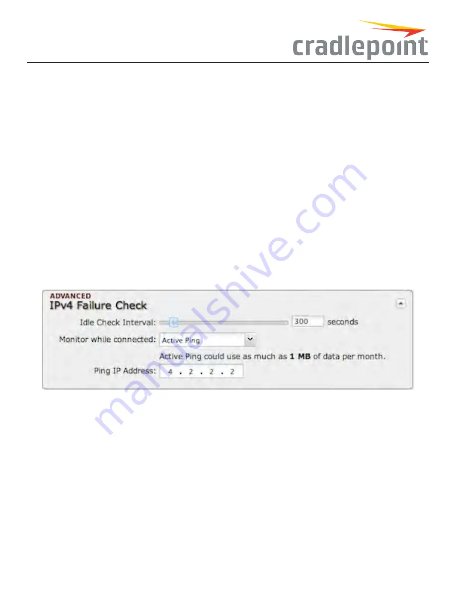
IPv4FailureCheck(Advanced)
If this is enabled, the router will check that the highest priority active WAN interface can get to the Internet even
if the WAN connection is not actively being used. If the interface goes down, the router will switch to the next highest priority interface available. If
this is not selected, the router will still failover to the next highest priority interface but only after the user has attempted to get out to the Internet
and failed.
Figure 104: IPv4 Failure Check Settings
IdleCheckInterval
: The amount of time between each check. (Default: 30 seconds. Range: 10-3600 seconds.)
Monitorwhileconnected
: (Default: Off) Select from the following dropdown options:
•
PassiveDNS
(modem only): The router will take no action until data is detected that is destined for the WAN. When this data is detected,
the data will be sent and the router will check for received data for 2 seconds. If no data is received the router behaves as described below
under
ActiveDNS
.
•
ActiveDNS
(modem only): A DNS request will be sent to the DNS servers. If no data is received, the DNS request will be retried 4 times
at 5-second intervals. (The first 2 requests will be directed at the Primary DNS server and the second 2 requests will be directed at the
Secondary DNS server.) If still no data is received, the device will be disconnected and failover will occur.
•
ActivePing
: A ping request will be sent to the Ping Target. If no data is received, the ping request will be retried 4 times at 5-second
intervals. If still no data is received, the device will be disconnected and failover will occur. When “Active Ping” is selected, the next line
gives an estimate of data usage in this form: “Active Ping could use as much as
9.3MB
of data per month.” This amount depends on the
IdleCheckInterval
.
80
Summary of Contents for COR IBR350
Page 7: ...Figure 3 COR IBR350 Lights Ports Figure 4 COR IBR350 SIM Door USB Antenna Connectors 7 ...
Page 14: ...Figure 12 Router UI Figure 13 Cradlepoint logo Figure 14 Quick links 14 ...
Page 18: ...Figure 19 Enterprise Cloud Manager Login Page 18 ...
Page 25: ...Figure 27 COR IBR350 Status Dashboard Figure 28 Cradlepoint Logo 25 ...
Page 29: ...Figure 32 Internet Connection Status Figure 33 Modem Status Figure 34 QoS Status 29 ...
Page 32: ...Figure 39 Failover Failback Load Banlance Statistics Figure 40 System Log 32 ...
Page 34: ...Figure 41 VPN Tunnel Status 34 ...
Page 43: ...Figure 57 Zone Firewall Settings Figure 58 Port Forwarding Rules 43 ...
Page 46: ...Figure 62 Remote Admin Access Figure 63 Add Edit Remote Admin Access 46 ...
Page 52: ...Figure 70 Add Network Filter Policy 52 ...
Page 53: ...Figure 71 Filter Rule Editer 53 ...
Page 56: ...Figure 74 Local IP Networks 56 ...
Page 58: ...Figure 76 IPv4 Settings Editor 58 ...
Page 60: ...Figure 77 IPv6 Settings Editor 60 ...
Page 61: ...Figure 78 Network Interface Editor 61 ...
Page 62: ...Figure 79 Local Network Access Editor 62 ...
Page 63: ...Figure 80 IPv4 DHCP Editor 63 ...
Page 65: ...Figure 82 IPv6 Network Adressing Editor 65 ...
Page 66: ...Figure 83 Multicast Proxy Editor Figure 84 Add Multicast Proxy 66 ...
Page 76: ...Figure 99 Static Routes Figure 100 Static Route Editor 76 ...
Page 86: ...Figure 111 Modem Settings 86 ...
Page 90: ...Figure 115 Modem Update Activation Figure 116 Modem Update Error 90 ...
Page 92: ...Figure 118 WAN Configuration Rules 92 ...
Page 96: ...Figure 122 Data Usage Rules Figure 123 Data Usage Rule Editor Page 1 96 ...
Page 99: ...Figure 127 Historical Data Usage Figure 128 Add Historical Data Usage 99 ...
Page 101: ...Figure 130 GRE Tunnel Editor 101 ...
Page 103: ...Figure 131 GRE Tunnel Toute Editor Figure 132 Keep Alive GRE TUnnel 103 ...
Page 106: ...Figure 135 Add VPN Tunnel 106 ...
Page 112: ...Figure 141 Add Edit VPN Tunnel IKE Phase 2 112 ...
Page 117: ...Figure 145 Local User Settings Figure 146 TACACS Settings 117 ...
Page 121: ...Figure 151 GPS Settings 121 ...
Page 126: ...Figure 156 GPS Client Settings 126 ...
Page 135: ...Figure 161 Create PKCS12 Format Certificates 135 ...
Page 138: ...Figure 163 Local Certificates Figure 164 Import PEM CA Certificate 138 ...
Page 141: ...Figure 168 Device Alert Configuration Figure 169 SMTP Mail Server Configuration 141 ...
Page 146: ...Figure 175 Device Control Figure 176 System Ping 146 ...
Page 148: ...Figure 179 Firmware System Config Restore Page 148 ...


