Schedule
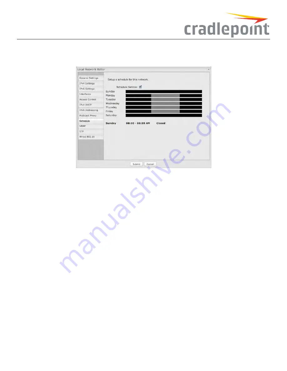
Set up a schedule for this network interface. This allows an interface to be enabled or disabled during specific hours of a day. For
example, use this to limit a Hotspot network to business hours.
Figure 85: Network Interface Scheduler
ScheduleService
: (Default: Disabled.) Select to enable. This will open a configurable chart for setting the schedule.
Each hour of the week is represented by a black or gray square. Black represents disabled, while gray represents enabled. Hover over a square to
reveal the hour it represents. Click on the squares to toggle between black and gray.
In the example shown, the network is enabled from 8-5 on Monday through Friday, but disabled at all other times.
Wired802.1X
Wired 802.1X: (requires hardware version 2.0) This allows you to configure an authentication server that will accept authentication
requests from devices attached to wired Ethernet ports. IEEE 802.1X defines the encapsulations of the Extensible Authentication Protocol (EAP).
Click
Enable802.1X
to require IEEE 802.1X authorization for the Ethernet ports associated with this network.
ReauthenticationPeriod
: EAP re-authentication period in seconds.
Authenticationsettings
•
AuthServerIP Address
: This is the IP address of the connected RADIUS server.
•
AuthServerMAC Address
: This is the hardware address of the connected RADIUS server’s interface.
NOTE:Ifyoudon’tknowtheMAC
addressfortheRADIUS server, enter00:00:00:00:00:00andtheservicewilltrytofindtheMAC addressfromthegivenIP address.
•
Port
: 1812 is common for the authentication port.
•
Password
: Assigned by the RADIUS server.
Accountingsettings
: Most of the accounting settings often match the authentication settings, depending on whether the RADIUS server is the
same for both authentication and accounting.
•
AcctServerIP Address
•
AcctServerMAC Address
•
Port
: 1813 is common for the accounting port.
•
Password
67
Summary of Contents for COR IBR350
Page 7: ...Figure 3 COR IBR350 Lights Ports Figure 4 COR IBR350 SIM Door USB Antenna Connectors 7 ...
Page 14: ...Figure 12 Router UI Figure 13 Cradlepoint logo Figure 14 Quick links 14 ...
Page 18: ...Figure 19 Enterprise Cloud Manager Login Page 18 ...
Page 25: ...Figure 27 COR IBR350 Status Dashboard Figure 28 Cradlepoint Logo 25 ...
Page 29: ...Figure 32 Internet Connection Status Figure 33 Modem Status Figure 34 QoS Status 29 ...
Page 32: ...Figure 39 Failover Failback Load Banlance Statistics Figure 40 System Log 32 ...
Page 34: ...Figure 41 VPN Tunnel Status 34 ...
Page 43: ...Figure 57 Zone Firewall Settings Figure 58 Port Forwarding Rules 43 ...
Page 46: ...Figure 62 Remote Admin Access Figure 63 Add Edit Remote Admin Access 46 ...
Page 52: ...Figure 70 Add Network Filter Policy 52 ...
Page 53: ...Figure 71 Filter Rule Editer 53 ...
Page 56: ...Figure 74 Local IP Networks 56 ...
Page 58: ...Figure 76 IPv4 Settings Editor 58 ...
Page 60: ...Figure 77 IPv6 Settings Editor 60 ...
Page 61: ...Figure 78 Network Interface Editor 61 ...
Page 62: ...Figure 79 Local Network Access Editor 62 ...
Page 63: ...Figure 80 IPv4 DHCP Editor 63 ...
Page 65: ...Figure 82 IPv6 Network Adressing Editor 65 ...
Page 66: ...Figure 83 Multicast Proxy Editor Figure 84 Add Multicast Proxy 66 ...
Page 76: ...Figure 99 Static Routes Figure 100 Static Route Editor 76 ...
Page 86: ...Figure 111 Modem Settings 86 ...
Page 90: ...Figure 115 Modem Update Activation Figure 116 Modem Update Error 90 ...
Page 92: ...Figure 118 WAN Configuration Rules 92 ...
Page 96: ...Figure 122 Data Usage Rules Figure 123 Data Usage Rule Editor Page 1 96 ...
Page 99: ...Figure 127 Historical Data Usage Figure 128 Add Historical Data Usage 99 ...
Page 101: ...Figure 130 GRE Tunnel Editor 101 ...
Page 103: ...Figure 131 GRE Tunnel Toute Editor Figure 132 Keep Alive GRE TUnnel 103 ...
Page 106: ...Figure 135 Add VPN Tunnel 106 ...
Page 112: ...Figure 141 Add Edit VPN Tunnel IKE Phase 2 112 ...
Page 117: ...Figure 145 Local User Settings Figure 146 TACACS Settings 117 ...
Page 121: ...Figure 151 GPS Settings 121 ...
Page 126: ...Figure 156 GPS Client Settings 126 ...
Page 135: ...Figure 161 Create PKCS12 Format Certificates 135 ...
Page 138: ...Figure 163 Local Certificates Figure 164 Import PEM CA Certificate 138 ...
Page 141: ...Figure 168 Device Alert Configuration Figure 169 SMTP Mail Server Configuration 141 ...
Page 146: ...Figure 175 Device Control Figure 176 System Ping 146 ...
Page 148: ...Figure 179 Firmware System Config Restore Page 148 ...


