


Computec
CDD6
EN
CDD6: user manual – rev.07
Page 15/74
3
Power supply connection
Nominal Supply Voltage: [100 – 240]Vac [50-60]Hz, single phase
Range: [115-20%, 230+30%]Vac
4
Final Checks
Verify that required signals are connected,
then apply the cover
.
For further information please refer to the paragraph 4.2
- Table 6: installation of electrical parts (Encoder version)
–
3.5
Check of electrical parts for magnetic switches applications
Ste
p
Operation
Description
0
Preliminary checks
Press OFF button on the door drive front panel.
Be sure that no power supply is present.
1
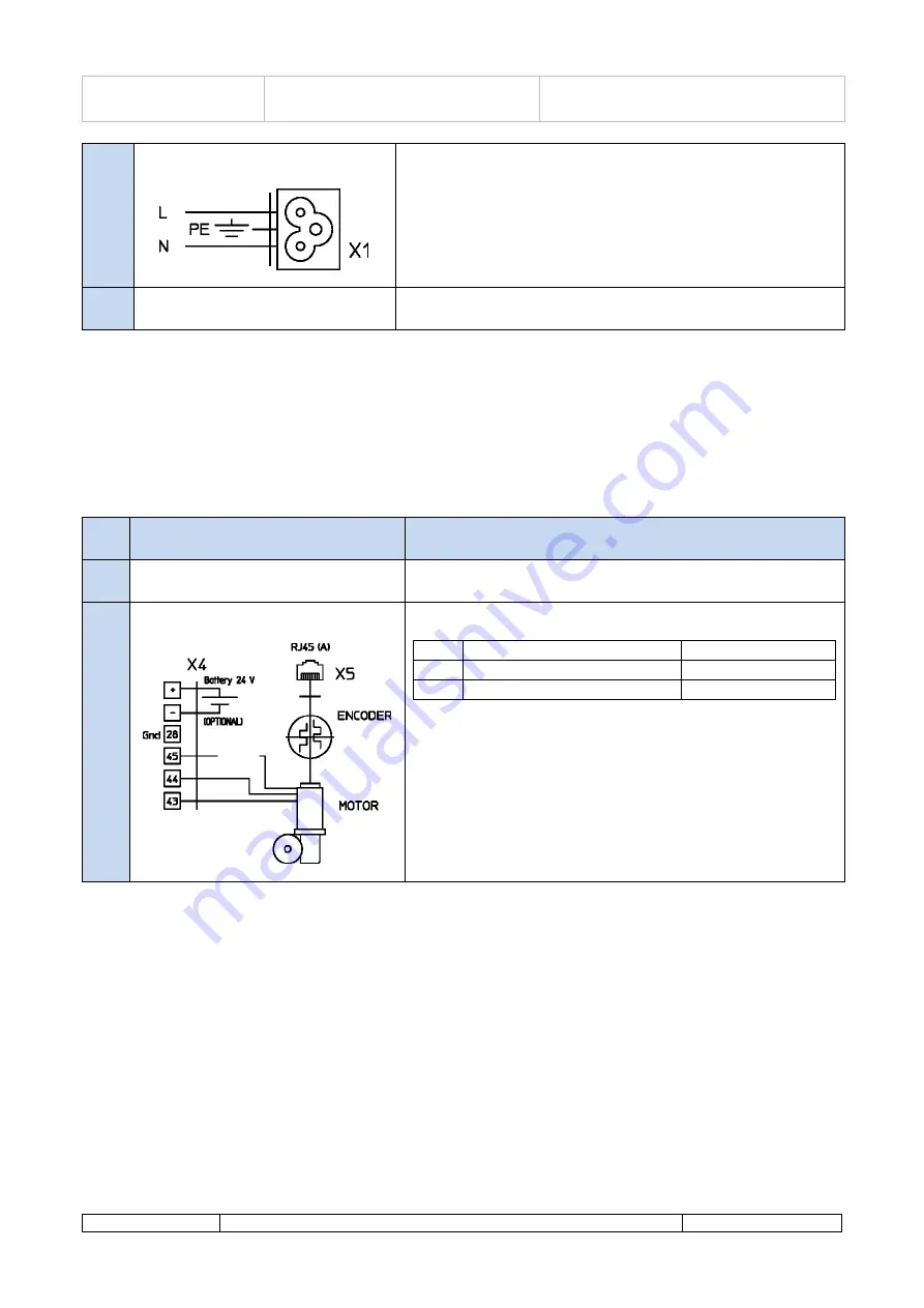
Motor Connections
1.Connect the motor cable to the pins of the X4 connector:
PIN
Description
Wire Color
43
Positive
Brown
44
Negative
White
Keep in any case the previous connection order, in case no
numbering rings are present, or in case the wires color is different
from the one described.
2.If present, connect the external battery kit to the positive (+) and
negative (-) pins of the X4 connector.