background image

.  .  .  .  .  .  .  .  .  .  .  .  .  .  .  .  .  .  .  .  .  .  .  .  .  .  .  .  .  .

xii


Preface

Writer:

  BJ PEREIRA 

Project:

 Preface 

Comments:

File Name:

C_PRE.DOC 

Last Saved On:

8/27/96 11:42 AM

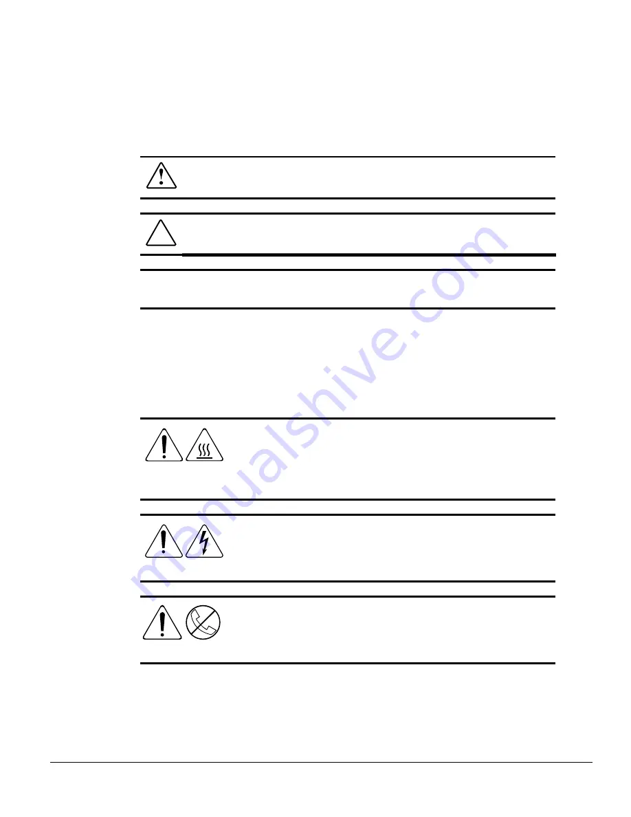
Symbols In Text

WARNING:

Text set off in this manner indicates that failure to follow

directions in the warning can result in bodily harm or loss of life.

CAUTION:

Text set off in this manner indicates that failure to follow

directions can result in damage to equipment or loss of information.

IMPORTANT:

Text set off in this manner presents clarifying information or specific

instructions.

NOTE:

Text set off in this manner presents commentary, sidelights, or interesting

points of information.

Symbols in Equipment

WARNING:  

Any surface or area of the equipment marked with

these symbols indicates the presence of a hot surface or hot
component. If this surface is contacted, the potential for injury
exists. To avoid risk of injury from a hot component, allow the
surface to cool before touching.

WARNING:  

Any surface or area of the equipment marked with

these symbols indicates the presence of electrical shock hazards.
Enclosed area contains no operator serviceable parts. To avoid risk
of injury from electrical shock hazards, do not open this enclosure.

WARNING:  

Any RJ-45 receptacle marked with these symbols

indicates a Network Interface Connection. To avoid risk of electrical
shock, fire, or damage to the equipment, do not plug telephone or
telecommunications connectors into this receptacle.

Summary of Contents for 2500 - ProLiant - 64 MB RAM

Page 1: ... NOTICE 0112 3 4 5 5 6 01127 8901 2 0 ...

Page 2: ...zed Reseller or Service Provider xiv Chapter 1 Compaq ProLiant 2500 Features Customer Support 1 1 Standard Features 1 2 Server Models with Compaq Processor Board and Intel Pentium Pro Processor 1 2 Pentium Pro Processor System Memory 1 2 Expansion Slots 1 2 Disk Controller 1 3 Network Controller 1 3 Mass Storage for Hot Pluggable Models 1 3 Mass Storage for Non Hot Pluggable Models 1 4 Standard In...

Page 3: ...port 2 1 Standard Features 2 2 Compaq Processor Board and Intel Pentium Pro Processor 2 2 System Memory 2 2 Expansion Slots 2 2 Disk Controller 2 3 Network Controller 2 3 Mass Storage 2 3 Standard Interfaces 2 4 Video 2 4 ROM 2 4 Power Supply 2 4 Warranty 2 4 Server Configuration and Management 2 5 Compaq SmartStart 2 5 Server Management 2 5 Compaq Insight Manager 2 6 Compaq System Configuration U...

Page 4: ...Internal Wiring and Hood Labels 3 7 Removing and Replacing the Processor Board Tray 3 8 Installing Security Provisions 3 9 Locating the Expansion Slot Locations 3 12 Installing an Expansion Board 3 13 Installing More Pentium Pro Memory 3 16 Installing Additional Mass Storage Devices 3 18 Installing External Storage Devices 3 24 Setting System Board and Processor Board Switches 3 24 Installing a Pr...

Page 5: ...y to the Rack 4 14 Measuring with the Template 4 14 Inserting Cage Nuts in the Rack Frame 4 16 Attaching the Mounting Bracket Assembly to the Rack 4 17 Attaching Component Rails to the Server 4 19 Attaching the Cable Management Arm Bracket 4 20 Loading the Rack Server 4 21 Attaching the Cable Management Arm 4 23 Attaching the Optional Cable Support 4 25 Cabling the Server 4 26 Powering Up and Conf...

Page 6: ...500 All Models B 2 ProLiant 2500R All Models B 3 Connector Interfaces B 4 Appendix C Power Cord Set Requirements General Requirements C 1 Country Specific Requirements C 2 Appendix D Regulatory Notices Appendix E Using the Internal CD ROM Drive Opening the Tray Automatically E 2 Opening the Tray Manually E 4 Index ...

Page 7: ...nd installation technical information by using the poster or the hood labels How this Manual is Organized This guide describes the features configuration diagnostics and technical specifications of your new server The manual is divided into the following chapters Chapter 1 Provides an overview of the ProLiant 2500 tower model server and its features Chapter 2 Provides an overview of the ProLiant 2...

Page 8: ...rea of the equipment marked with these symbols indicates the presence of a hot surface or hot component If this surface is contacted the potential for injury exists To avoid risk of injury from a hot component allow the surface to cool before touching WARNING Any surface or area of the equipment marked with these symbols indicates the presence of electrical shock hazards Enclosed area contains no ...

Page 9: ...hardcopy documents Compaq Web Site http www compaq com Compaq Authorized Reseller or Service Provider Compaq CDs Compaq Systems Reference Library CD Compaq Systems Reference Library CD is located in the Reference Information pack and includes the following online documents Compaq SmartStart CD Compaq SmartStart CD is located in the Server Setup and Management pack and contains ...

Page 10: ...u will need to log onto the Internet to access the Compaq Web Site http www compaq com Compaq Authorized Reseller or Service Provider Call one of the technical support telephone numbers listed below to locate your nearest Compaq Authorized Reseller or Service Provider Compaq Worldwide Technical Support Telephone Numbers Location Voice FAX APD 65 7503030 65 7504909 Argentina 54 1 313 3100 54 1 313 ...

Page 11: ...36 1 201 8776 36 1 201 9696 India 91 80 559 6023 Italy 392 57 90300 392 575 00686 Japan 0120 101589 81 3 5402 5959 Korea 82 2 523 3575 82 2 3471 0321 Malaysia 603 718 1636 Mexico 525 229 7910 525 229 7988 Netherlands 06 91681616 06 8991116 New Zealand 649 307 3969 Norway 22 072 020 22 072 021 Poland 48 2 630 3535 48 2 630 3553 Portugal 351 1 4120132 351 1 4120654 Singapore 65 7503030 65 7504909 So...

Page 12: ...ivering Error Checking and Correcting Memory PCI architecture hot pluggable drives integrated Fast Ethernet Integrated Remote Console and integrated Wide Ultra SCSI Controller on the PCI Local Bus The new ProLiant 2500 server chassis significantly improves system serviceability and upgradability CZR 001 EPS Figure 1 1 Compaq ProLiant 2500 Customer Support Compaq servers are backed by comprehensive...

Page 13: ...g Memory uses an encoding scheme for memory error detection and correction Specifically this feature detects and corrects for single bit memory errors 32 MB EDO buffered 64 bit system memory expandable to 1 GB Supports 60 ns or faster EDO or FASTPAGE buffered 32 64 128 or 256 MB 4 K refreshed DIMMs Expansion Slots Six expansion slots two dedicated PCI slots and four shared PCI EISA slots The Exten...

Page 14: ...controller on the PCI local bus Features of the controller include the RJ 45 connector for 10BaseT or 100TX Ethernet and the AUI connector for 10Base2 Ethernet For information concerning the integrated network controller refer to the Systems Reference Library CD included in the Reference Information pack Mass Storage for Hot Pluggable Models Maximum of nine drive bays four non hot pluggable in rem...

Page 15: ...able media drive bay occupied by IDE CD ROM drive Two half height vacant 5 25 removable media drive bays Supports up to four 1 6 non hot pluggable drives in the front drive cage Standard Interfaces Wide Ultra SCSI Serial 2 Video Parallel Keyboard Mouse Ethernet 10BaseT or 100TX RJ 45 and 10Base2 AUI Video Integrated Video Controller provides maximum resolution of 1024 x 768 non interlaced resoluti...

Page 16: ...de Warranty Prefailure warranty on processors memory and hard drives Server Configuration and Management Compaq offers an extensive set of features and optional tools to support effective server management and configuration These features fall into the categories listed below SmartStart Server Management Compaq Insight Manager Compaq System Configuration Utility Compaq Integrated Remote Console ...

Page 17: ...ncluded in the shipping box Server Management Server management features provide in depth monitoring analysis and control of the fault tolerance performance and configuration aspects of the servers Server management features include Server Parameter Tracking Server Fault Tolerance Recovery Services Remote Services Features For information concerning server management features refer to the Systems ...

Page 18: ...ide range of configuration activities including the following Configures EISA and PCI boards automatically Provides switch and jumper settings Resolves resource conflicts in areas such as memory port addresses and interrupts IRQs Manages the installation of memory processor upgrades and mass storage devices such as hard drives tape drives and diskette drives Sets and stores power on features like ...

Page 19: ...es access to system configuration Uses out of band communication with dedicated management modem installed in the server For information concerning the standard Integrated Remote Console refer to the Integrated Remote Console User Guide included in the shipping box Security Features Security features are as follows Keyboard Password Administrator Password Network Server Mode QuickLock Diskette Dri...

Page 20: ... to the Systems Reference Library CD and the SmartStart CD included in the shipping box Diagnostic Tools The software and firmware diagnostic tools available for your use are Power On Self Test POST Diagnostics DIAGS ROMPaq utilities to upgrade flash ROMs Automatic Server Recovery ASR 2 For information concerning Compaq diagnostic tools refer to the Systems Reference Library CD included in the Ref...

Page 21: ...ivering Error Checking and Correcting Memory PCI architecture hot pluggable drives integrated Fast Ethernet Integrated Remote Console and integrated Wide Ultra SCSI Controller on the PCI Local Bus The new ProLiant 2500R server chassis significantly improves system serviceability and upgradability CZR 053 eps Figure 2 1 Compaq ProLiant 2500R Customer Support Compaq servers are backed by comprehensi...

Page 22: ...ncoding scheme for memory error detection and correction Specifically this feature detects and corrects for single bit memory errors 32 MB EDO buffered 64 bit system memory expandable to 1 GB Supports 60 ns or faster EDO or FASTPAGE buffered 32 64 128 or 256 MB 4 K refreshed DIMMs Expansion Slots Six expansion slots two dedicated PCI slots and four shared PCI EISA slots The Extended Industry Stand...

Page 23: ...d 10 100 TX UTP controller on the PCI local bus Features of the controller include an RJ 45 connector for 10BaseT Ethernet and an AUI connector for 10Base2 Ethernet For information concerning the integrated network controller refer to the Systems Reference Library CD included in the Reference Information pack Mass Storage Maximum of nine drive bays four non hot pluggable in removable media drive a...

Page 24: ...o Controller provides maximum resolution of 1024 x 768 non interlaced resolution 16 to 256 colors depending on graphics mode Supports SVGA VGA and EGA graphics resolution ROM Software upgradable firmware ROMPaq Utility used to upgrade ROM Power Supply 325 W power supply Warranty Three Year On Site Limited Worldwide Warranty Prefailure warranty on processors memory and hard drives ...

Page 25: ... Microsoft SCO and IBM system software SmartStart uses a step by step process to configure the server and to load the system software thereby achieving a well integrated server to ensure maximum dependability and supportability The SmartStart CD also holds the Compaq System Configuration Utility and ROMPaq For information concerning SmartStart refer to the Server Setup and Management pack included...

Page 26: ... robust set of management capabilities Compaq s Full Spectrum Fault Management prevents faults before they happen keeps the system up and running in the unlikely event of a failure and delivers rapid server recovery to normal operation after a fault For information concerning Compaq Insight Manager refer to the Server Setup and Management pack included in the shipping box Compaq System Configurati...

Page 27: ...ms Reference Library CD included in the shipping box Compaq Integrated Remote Console The standard Compaq Integrated Remote Console performs a wide range of configuration activities including the following Accessible using ANSI terminal Operates independently of the operating system Provides for remote server reboot Provides access to system configuration Uses out of band communication with dedica...

Page 28: ...nformation concerning server security features refer to the Systems Reference Library CD and the SmartStart CD included in the shipping box Diagnostic Tools The software and firmware diagnostic tools available for your use are Power On Self Test POST Diagnostics DIAGS ROMPaq utilities to upgrade flash ROMs Automatic Server Recovery ASR 2 For information concerning Compaq diagnostic tools refer to ...

Page 29: ...d when installing your ProLiant 2500 server for the first time 1 Select a site and unpack the server keyboard mouse and monitor monitor not supplied 2 Order SmartStart Activation Keys if purchasing operating system from Compaq Optional For ordering information refer to the Server Setup and Management pack shipped with your server 3 Install any PCI and EISA expansion boards 4 Connect cables keyboar...

Page 30: ...will be prompted to turn the server off install any ISA boards any switch settings required will be provided by the System Configuration utility and then boot the server again from the SmartStart program Selecting a Site Ensure that the installation site you select has the following features Sturdy level installation site that includes dedicated and properly grounded circuits air conditioning and ...

Page 31: ...Materials Locate the following materials that were shipped with your new server ProLiant 2500 Server Keyboard Mouse Power cord Documentation Inside the Server Most of the option installation and setup instructions are located on the hood labels which are attached to the inside of the Side Access Panel and the Top Access Panel Hardware Documentation and Software Packs Inside the Shipping Box Server...

Page 32: ...ide Access Panel or the Expansion Board Hood Label located on the inside of the Top Access Panel The Compaq 2500 s new server chassis facilitates the installation of hardware upgrades Most hardware options are installed on the system board on the processor board and in the drive bay area To Gain Access To You Will Need To System board Open the Front Bezel and remove the Top Access Panel Expansion ...

Page 33: ...ion Opening the Front Bezel To open the Front Bezel 1 If the keylock is locked turn the keylock 2 Open the Front Bezel front door to the right CZR 002 EPS Figure 3 1 Opening the Front Bezel Removing Top Access Panel to Locate System Board Expansion Slots and Hood Labels To remove the Top Access Panel 1 If the computer is on turn it off and disconnect the power cord 2 Disconnect any other external ...

Page 34: ...ess Panel removed The Top Access Panel is an integral part of the cooling system and removing it while the system is running may adversely affect data integrity CZR 004 EPS Figure 3 2 Sliding the Top Access Panel 7 Turn the Top Access Panel over to locate the System Board Hood Label and the Expansion Board Hood Label NOTE These hood labels provide instructions on installing expansion boards and se...

Page 35: ...he Side Access Panel toward the rear of the unit 0 5 inch 1 5 cm 6 Lift and remove the panel CAUTION Do not operate the server with the Side Access Panel removed The Side Access Panel is an integral part of the cooling system and removing it while the system is running may adversely affect data integrity CZR 003 EPS Figure 3 3 Removing the Side Access Panel 7 Turn the Side Access Panel over to loc...

Page 36: ...ected to the processor board tray Refer to figure below CAUTION If a security screw is installed in the side of the processor board tray remove the screw before opening the tray CAUTION To prevent damage to internal wiring contact your Authorized Compaq Reseller before using the system board ejector lever 3 Open the processor board tray CZR 007 EPS 2 3 1 System Board Tray Ejector Lever Processor B...

Page 37: ...t however a recommended procedure for powering off the server Installing Security Provisions The ProLiant 2500 is equipped with four unique security access provisions one keylock for the Front Bezel and one locking screw each for the system board tray the processor board tray and the fan door 1 If the computer is on turn it off and disconnect the power cord 2 Disconnect any other external equipmen...

Page 38: ...rd tray and fan door remove the three security screws located at the front of the side chassis CZR 051a eps Figure 3 5 Removing Three Security Screws from Front Left Side of Chassis 5 Reinstall the screws at the rear of the chassis CZR 051 eps Figure 3 6 Installing Three Security Screws 6 Replace the Side Access Panel ...

Page 39: ... 3 11 Compaq ProLiant 2500 Servers Installation Guide 7 Close the Front Bezel and turn the keylock to lock the bezel CZR 032 EPS Figure 3 7 Securing Front Bezel with Keylock ...

Page 40: ...1 4 Two dedicated PCI local bus expansion slot slots 5 and 6 NOTE Although there are two physical connectors one EISA and one PCI for each shared PCI EISA slot the connectors are placed so that only one of the connector slots can have a board installed at a time Expansion boards can be installed in the following expansion board slot locations Slot 1 CZR 023 EPS Slot 2 Slot 3 Slot 4 Slot 5 Slot 6 S...

Page 41: ...rocedure refer to the Hardware Installation and Configuration poster included in the shipping box or to the Expansion Board Installation Hood Label located on the inside of the Side Access Panel 1 If the computer is on turn it off and disconnect the power cord 2 Disconnect any other external equipment connected to the computer 3 Remove the Top Access Panel 4 Press on the top of the expansion slot ...

Page 42: ... 3 14 Overview of Installing ProLiant 2500 Server and Hardware Options 6 Insert the expansion board CZR 037a eps Figure 3 10 Inserting Expansion Board ...

Page 43: ...ose the expansion slot latch to secure the board CZR 052 eps Figure 3 11 Securing Expansion Board 8 Close up the server 9 Reconnect any external peripherals and the power cord 10 Turn on the computer 11 Run the Compaq System Configuration utility if necessary ...

Page 44: ...to one of the following installation sources For a text and illustration procedure refer to the installation documentation that came with the option kit For a text only overview of the procedure refer to the procedure below For an illustration overview of the procedure refer to the Hardware Installation and Configuration poster included in the shipping box or to the Processor Board Hood Label loca...

Page 45: ... the socket NOTE A memory module can only be installed in one way Match the notch on the module with the tab on the memory socket Push the module down into the socket ensuring that the module is fully inserted and properly seated 8 Close the DIMM socket latches 9 Reinstall the processor board tray 10 Reconnect any external peripherals and the power cord 11 Turn on the computer ...

Page 46: ...ch or 1 6 inch SCSI hard drives can be installed in the hot pluggable drive cage SCSI IDs 0 4 The drive cage is capable of configuring a maximum of Five 1 inch hard drives or Two 1 6 inch hard drives and one 1 inch hard drive The figure below shows five 1 inch hard drives installed in the hot pluggable drive cage CZR 026 EPS 0 1 2 3 4 5 6 Figure 3 13 SCSI IDs Locations for Hot Pluggable Models SCS...

Page 47: ...led in the vacant removable media drive bays SCSI IDs 4 and 5 Non hot pluggable models have a drive cage SCSI IDs 0 3 capable of configuring a maximum of four 1 6 inch hard drives CZR 026a EPS 4 5 0 1 2 3 Figure 3 14 SCSI ID Locations for Non Hot Pluggable Models SCSI IDs 4 and 5 are non hot pluggable SCSI hard drives on the Integrated Wide Ultra SCSI Controller on the PCI Bus must be either inter...

Page 48: ...f height removable storage devices such as tape or hard drives can be installed in the bottom two removable media drive bays Also one full height storage device such as a DLT tape drive can be installed in the area occupied by the bottom removable media drive bays To install a device in this area and to cable the device refer to the installation documentation that came with the drive The illustrat...

Page 49: ... pluggable hard drive is set as the bay number Bay 0 SCSI ID 0 If only one SCSI hard drive is used it should be installed in the lowest numbered bay Compaq SCSI non hot plug cables for the Compaq ProLiant 2500 are terminated Be sure to remove all terminating jumpers from third party SCSI devices Run System Configuration Utility after installing a drive SCSI hard drives on the Integrated Wide Ultra...

Page 50: ... hard drive first review the installation documentation that came with the drive The following illustrations provide only an overview of a hard drive installation CZR 030 EPS 3 1 2 Figure 3 17 Opening Ejector Levers and Inserting Hard Drive CZR 031 EPS Locking Hinge See Caution Below Figure 3 18 Closing Ejector Levers to Secure Hard Drive in Drive Cage ...

Page 51: ...followed the server will not recognize the hard drive Installing Hard Drives in the Non Hot Pluggable Drive Cage To install a non hot pluggable hard drive refer to the installation documentation that came with the drive The following illustration and steps provide only an overview of this installation CZR 047 EPS Figure 3 19 Installing Non Hot Pluggable Hard Drive 1 Connect the signal and power ca...

Page 52: ...tation that came with the external storage device The following illustration provides only an overview of this installation CZR 034 EPS Figure 3 20 Connecting External Mass Storage Devices Setting System Board and Processor Board Switches To set system board and processor board switch settings refer to one or more of the following documents Hardware Installation and Configuration poster shipped in...

Page 53: ... or to the Processor Board Hood Label located on the inside of the Side Access Panel The processor installation procedure below is text only To install a processor 1 If the computer is on turn it off and disconnect the power cord 2 Disconnect any other external equipment connected to the computer 3 Remove the processor board tray 4 Place the processor board tray component side up on a flat surface...

Page 54: ...of each connector WARNING To reduce the risk of electrical shock or fire do not plug telecommunications telephone connectors into the Network Interface Card NIC receptacles CZR 009 EPS 1 2 3 4 5 12 11 10 9 8 7 6 Figure 3 21 Location of Rear Panel Connectors and LEDs Ref Connector or LED Ref Connector or LED 1 Parallel Connector 7 Mouse Connector 2 Serial Connector 8 Keyboard Connector hot pluggabl...

Page 55: ...t operator as possible When you need to disconnect power to the equipment be sure to unplug the power cord from the power outlet NOTE Do not place anything on power cords or cables Arrange them so that no one may accidentally step or trip over them Do not pull on a cord or cable When unplugging from the electrical outlet grasp the cord by the plug 1 Slide the power switch cover plate top the right...

Page 56: ...onfiguration activities including the following Configures EISA and PCI boards automatically Provides switch and jumper settings Resolves resource conflicts in areas such as memory port addresses and interrupts IRQs Manages the installation of memory processor upgrades and mass storage devices such as hard drives tape drives and diskette drives Sets and stores power on features like date and time ...

Page 57: ...cess door by pressing on the left side of the door Fully open the door to access the CD ROM drive CZR 042 EPS 1 2 Figure 3 23 Opening the Removable Media Access Door 2 Open the CD ROM tray by pressing the load unload button on the front panel of the drive Refer to Appendix E Using the Internal CD ROM Drive for CD ROM drive user instructions ...

Page 58: ... button 5 When the busy indicator turns green the drive is ready to receive commands and data may be retrieved from the disc Using Diagnostics Tools The software and firmware diagnostic tools available for your use are Power On Self Test POST Diagnostics DIAGS ROMPaq utilities to upgrade flash ROMs Automatic Server Recovery ASR 2 For information concerning Compaq diagnostic tools refer to the Syst...

Page 59: ... during the Product Interviews stage of the SmartStart configuration process Refer to the Server Setup and Management pack included in the shipping box Routine Maintenance For information concerning routine maintenance and safety precautions refer to the Systems Reference Library CD included in the Reference Information pack of the shipping box ...

Page 60: ...o the rack How to install the server into the rack How to cable the server How to access the internal components of the rack mounted server You may choose Compaq s optional installation service to install your rack products See Optional Installation Service at the end of this chapter CZR4 001 EPS Figure 4 1 ProLiant 2500R installed in rack For more information about Compaq rack mountable products ...

Page 61: ...of all the Compaq parts and part numbers that are required for complete installation Rack Mountable Compaq ProLiant Server Installation Video This video is about thirty minutes long and contains handy tips and tricks to help you efficiently and safely install your rack mountable products Rack Warnings and Precautions WARNING To avoid the risk of personal injury or damage to the equipment at least ...

Page 62: ... the equipment a minimum of two people MUST lift the server into the rack The server weighs about 50 pounds 22 6 kilograms If the unit is to be loaded above chest level a third person must assist in aligning the rails while the other two support the unit WARNING To reduce the risk of personal injury from hot surfaces allow the hot plug drives and internal system components to cool before touching ...

Page 63: ...l follow to install your rack model ProLiant 2500R server 1 Select an appropriate site for your rack See the Rack Planning and Installation Guide for site selection criteria 2 Unpack the server and rack mounting hardware 3 Install any EISA and or PCI expansion boards in the server See the options kits for detailed instructions To make the server lighter and more manageable do not install drives in...

Page 64: ...nfiguration Utility 11 When the System Configuration Utility is completed turn off the server install any other options such as additional memory hard drives external storage devices and ISA boards The System Configuration Utility provides required switch settings 12 Order Activation Keys 13 Register your server For complete details on the SmartStart program read the SmartStart installation card i...

Page 65: ...ountable server Locating Materials All of the equipment needed to install the ProLiant 2500R server in the rack is included with the rack and with the server CZR4 002 eps Figure 4 2 Rack mounting hardware included with the server Contents of the rack model server box include Compaq ProLiant 2500R server Rack mounting hardware One pair 22 inch slide rail assemblies Cable management arm bracket ...

Page 66: ...ck Hardware Installation Poster SmartStart Documentation Package Rack Planning and Installation Guide Rack Builder program Rack Installation Video CompaqCare folder Compaq Product Quality Statements Owner s Registration folder In addition to these supplied items you may need Phillips screwdriver Slotted screwdriver Application software diskettes such as SmartStart Options to be installed such as O...

Page 67: ...t one rack mountable server CZR4 003 eps Figure 4 3 Rack mounting brackets alignment tabs identify the front flanges Each slide rail assembly consists of an outer bracket rail and an inner component rail see the following figure These pieces can be separated the bracket rails attach to the rack mounting brackets shown in the previous figure and the component rails attach to the sides of the server...

Page 68: ...mounting bracket before attaching the mounting bracket assembly to the rack This way the joined mounting bracket and bracket rail can be fastened to the rack as one assembly Attaching the Bracket Rail to the Mounting Bracket 1 Unpack the hardware mounting kit Lay the two piece slide rail assembly outer bracket rail and inner component rail and fasteners on a flat surface along with the mounting br...

Page 69: ...his piece out of each bracket rail as shown in the following figure CZR4 005 eps Figure 4 5 Removing the component rail from the bracket rail 3 Put the component rails to one side You will attach them to the rack server chassis later in the section Attaching Component Rails to the Server The next figure shows the separated bracket rail with its inner sliding piece and the flat one piece component ...

Page 70: ...et rail top and component rail The bracket rail consists of a fixed outer rail that screws to the rack mounting bracket and an inner slide on a steel ball bearing movement This inner slide does not detach CZR4 007 eps Figure 4 7 Bracket rail with inner slide The front of the rail is highlighted ...

Page 71: ... back end of the bracket rail and the front hole accessible through a slot in the inner slide 6 Fasten the bracket rail to the mounting bracket with two 8 32 x 1 4 inch slotted screws Do not use nuts or washers with the screws See step of the following figure 7 Adjust the inner slide to access the other two screw holes one at a time through the slotted opening in the inner slide Use two more 8 32 ...

Page 72: ...ing the bracket rail to the mounting bracket You will use a total of five 8 32 x 1 4 inch slotted screws to fasten the bracket rail to the mounting bracket When all five screws are fastened the mounting bracket and bracket rail form a mounting bracket slide assembly that you will attach to the rack ...

Page 73: ...nd stabilizers Measuring with the Template The template provided with the server offers an easy and reliable way to properly position the server in the rack Use the tabs on the template to suspend it from the lower hole of a two hole set of perforations in the vertical side rails Pencil mark the attachment points for the mounting bracket assemblies the cage nuts for the face plate thumb screws and...

Page 74: ...for the thumb screws that will secure the server s face plate to the front of the rack Align the template carefully with the holes on the rack to determine the exact placement of the screws 2 When you mark the positioning of the mounting bracket screws also mark the positioning in the front of the rack for the cage nuts These are two slots marked C on the template The cage nuts will hold the thumb...

Page 75: ...op of the template This will help you align a template for the next component Inserting Cage Nuts in the Rack Frame After marking the positions for the fasteners in both the front and back of the rack use the fitting tool to insert cage nuts on the inside of the rails at the marked locations The cage nuts and fitting tool are included in the hardware kit supplied with the rack 1 Position the cage ...

Page 76: ...of the cage nut Figure 4 10 Inserting cage nuts 4 Using the fitting tool as a lever pry the cage nut into position 5 Repeat for each cage nut Attaching the Mounting Bracket Assembly to the Rack The tabs on the front of the mounting bracket help to align it with the front of the rack frame Cage nuts are not used for the front attachment of the mounting bracket ...

Page 77: ... bracket Do not use washers CZR4 011 eps Figure 4 11 Attaching mounting bracket assembly to the front of the rack 2 Carefully align the mounting bracket assembly with the rear rack frame 3 Secure the back end of the mounting bracket assembly to the back corner brace of the rack with one M6 x 1 0 12L Phillips screw through the bottom hole of the bracket and the cage nut as shown in the following fi...

Page 78: ...ies to the rack prepare the server for mounting in the rack Attaching Component Rails to the Server 1 Place the tab on a component rail at the front of the server chassis The holes in the component rail will line up only one way with the chassis 2 Attach the flat side of a component rail to each side of the server chassis with five 8 32 x 1 4 inch Phillips screws Do not use washers with the screws...

Page 79: ...ing the Cable Management Arm Bracket The cable management arm bracket fastens to the top right rear of the rack server s chassis The bracket provides an attachment point for the cable management arm from the server to the rear frame of the rack Attach the cable management arm bracket to the back of the server with two 6 32 x 1 4 Phillips screws ...

Page 80: ...ts is perfectly aligned and installed and that the server fits before you continue WARNING To avoid the risk of personal injury or damage to the equipment a minimum of two people MUST lift the server into the rack The server weighs 50 pounds 22 6 kilograms If the unit is to be loaded above chest level a third person must assist in aligning the rails while the other two support the unit IMPORTANT T...

Page 81: ...efully align the server s component rails with the rack s slide rails and slide the server into the rack CAUTION Be sure to keep the component parallel to the floor when sliding the component rails into the slide rails Tilting the component up or down could result in damage to the rails CZR4 015 EPS Figure 4 15 Loading the rack server ...

Page 82: ...end the component until the latches lock To return the server to the rack depress the latches and slide the server into the rack 4 Secure the server face plate to the front of the rack by screwing the thumb screws into the cage nuts 5 Tighten the thumb screws before you close the rack door to prevent the door from hitting protruding thumb screws Attaching the Cable Management Arm A double hinged c...

Page 83: ...d the server into the rack attach one end of the cable management arm to the server s cable management arm bracket using two M6 x 1 0 12L Phillips screws Align the arm to the bracket as shown in the following figure CZR4 016 EPS Figure 4 16 Attaching the cable management arm to the cable management arm bracket 3 Align the other end of the cable management arm on the outside of the rear brace of th...

Page 84: ...o and from the server are tied to this support which allows the server cables to stretch from the right rear of the server across to the cable channel on the other side of the rack where the other cables are all bundled in the cable channel The cable support is needed only if you intend to route cables from one side of the rack to a cable channel on the other side of the rack Attach the cable supp...

Page 85: ...2500R Server and Hardware Options CZR4 018 EPS Figure 4 18 Attaching the cable support to the rack Cabling the Server 1 Plug the power cable into the server CZR4 019 EPS Figure 4 19 Cabling through the cable management arm and cable support ...

Page 86: ... 4 27 Compaq ProLiant 2500 Servers Installation Guide 2 Plug in any remaining cables for example network cables or SCSI cables CZR4 020 EPS Figure 4 20 Routing and securing the cables ...

Page 87: ...he opposite cable channel 6 Extend the bundled cables down the rack s cable channel Before loading another component be sure to secure the server to the rack using the face plate thumb screws Powering Up and Configuring the Server After the cables have been connected you are ready to power up the server Refer to Chapter 3 Overview of Installing ProLiant 2500 Server and Hardware Options for the pow...

Page 88: ...allation Guide Servicing the Processor Board Swing the double hinged cable management arm to one side to gain access to the processor board CZR4 021 EPS Figure 4 21 Moving the double hinged cable management arm to access the processor board ...

Page 89: ...rd the back of the server Optional Installation Service The installation service covers the entire hardware installation from unpacking the components to routing the cables and running a test of the system In the United States Compaq will make all of the arrangements to have the rack system installed by qualified Guaranteed Service Providers An order form with pricing is available from PaqFax the ...

Page 90: ...n a grounded surface before removing them from their containers Avoid touching pins leads or circuitry Always be properly grounded when touching a static sensitive component or assembly Grounding Methods There are several methods for grounding Use one or more of the following methods when handling or installing electrostatic sensitive parts Use a wrist strap connected by a ground cord to a grounde...

Page 91: ...not have any of the suggested equipment for proper grounding have an Authorized Compaq Reseller install the part NOTE For more information on static electricity or assistance with product installation contact your Authorized Compaq Reseller ...

Page 92: ...cations and Connector Interfaces This appendix provides operating and performance specifications for the following Compaq ProLiant components Compaq ProLiant 2500 all models Compaq ProLiant 2500R all models For other specifications refer to the Systems Reference Library CD ...

Page 93: ...0 lb 22 68 kg Input Requirements Rated Input Voltage 100 to 240 VAC Rated Input Frequency 50 60 Hz Rated Input Current 6 3 A Power Supply Output Power Rated Steady State Power 325 W Maximum Peak Power 425 W Temperature Range Operating 50 to 95 F 10 to 35 C Shipping 22 to 122 F 30 to 50 C Relative Humidity noncondensing Operating 8 to 90 8 to 90 Nonoperating 5 to 95 5 to 95 Maximum Wet Bulb Tempera...

Page 94: ...d 50 0 lb 22 68 kg Input Requirements Rated Input Voltage 100 to 240 VAC Rated Input Frequency 50 60 Hz Rated Input Current 6 3 A Power Supply Output Power Rated Steady State Power 325 W Maximum Peak Power 425 W Temperature Range Operating 50 to 95 F 10 to 35 C Shipping 22 to 122 F 30 to 50 C Relative Humidity noncondensing Operating 8 to 90 8 to 90 Nonoperating 5 to 95 5 to 95 Maximum Wet Bulb Te...

Page 95: ...erfaces Connector Interfaces For the pinouts and signals of these connector interfaces refer to the Systems Reference Library CD Keyboard hot pluggable Pointing Device Mouse Serial 2 Parallel Monitor SCSI 2 Connector Ethernet RJ 45 and AUI ...

Page 96: ...he server For more information on power cord set requirements contact your Authorized Compaq Dealer General Requirements The requirements listed below are applicable to all countries The length of the power cord must be at least 6 00 feet 1 8 m and a maximum of 8 feet 2 4 m The power cord set must be approved by an acceptable accredited agency responsible for evaluation in the country where the po...

Page 97: ...ble cord must be HAR Type HO5VV F 3 conductor 1 0 mm2 conductor size Power cord set fittings appliance coupler and wall plug must bear the certification mark of the agency responsible for evaluation in the country where it will be used 2 Flexible cord must be Type SVT or equivalent No 18 AWG 3 conductor Wall plug must be a two pole grounding type with a NEMA 5 15P 15A 125V 3 Appliance coupler flex...

Page 98: ...rating label on the device shows which class A or B the equipment falls into Class B devices have an FCC ID on the label Class A devices do not have an FCC ID on the label Once the class of the device is determined refer to the following corresponding statement Class A Equipment This equipment has been tested and found to comply with the limits for a Class A digital device pursuant to Part 15 of t...

Page 99: ... one or more of the following measures Reorient or relocate the receiving antenna Increase the separation between the equipment and receiver Connect the equipment into an outlet on a circuit different from that to which the receiver is connected Consult the dealer or an experienced radio or television technician for help Canadian Notice This Class B digital apparatus meets all requirements of the ...

Page 100: ...e 89 336 EEC and the Low Voltage Directive 73 23 EEC issued by the Commission of the European Community Compliance with these directives implies conformity to the following European Norms EN55022 CISPR 22 Electromagnetic Interference EN50082 1 IEC801 2 IEC801 3 IEC801 4 Electromagnetic Immunity EN60950 IEC950 Product Safety Japanese Notice ...

Page 101: ...ed with a battery powered Real Time Clock circuit There is a danger of explosion and risk of personal injury if the battery is incorrectly replaced or mistreated Do not attempt to recharge the battery disassemble it immerse it in water or dispose of it in fire Replacement is to be done by an Authorized Compaq Service Provider using the Compaq spare designated for this product For more information ...

Page 102: ...ns CFR 1040 10 para b item 5 This means that this is a Class of laser products that does not emit hazardous laser radiation this is possible only because the laser beam is totally enclosed during all modes of customer operation The laser produces a beam that if looked into could cause eye damage Installation and Service procedures must be followed exactly as written without change WARNING Use of c...

Page 103: ...ee 1 5 Degree Output Power Less than 0 2mW or 10 869 W m 2 sr 1 Polarization Circular Numerical Aperture 0 45 0 04 Only authorized technicians trained by Compaq should attempt to repair this equipment All troubleshooting and repair procedures are detailed to allow only subassembly module level repair Because of the complexity of the individual boards and subassemblies no one should attempt to make...

Page 104: ... Figure E 1 Internal CD ROM Front Panel Table E 1 Internal CD ROM Ref Component Function Headphone Jack Connects the headphone Headphone Volume Control Increases or decreases the headphone volume Busy Indicator Turns green when a disc is present flashes amber when the drive is reading a CD Disc Tray Slides in and out Holds the CD in place Manual Eject Hole Allows you to manually eject a CD if the ...

Page 105: ...ton Ensure plenty of clearance for the tray to open and close 1 With your computer turned on open the removable media access door by first pressing on the left side of the door Fully open the door to access the CD ROM drive CZR 042 EPS 1 2 Figure E 2 Opening the Removable Media Access Door 2 Open the Internal CD ROM tray by pressing the load unload button on the front panel of the drive ...

Page 106: ...sing the load unload button The drive performs a diagnostic check and automatically begins reading the table of contents The busy indicator turns amber while the drive reads the table of contents NOTE The tray automatically opens if the disc is upside down not properly nested in the tray or if any other condition prevents the drive from reading the disc 5 When the busy indicator turns green the dr...

Page 107: ...cidental damage to the disc If the load unload button is disabled by the application software it will not operate CAUTION Before beginning this procedure turn off the power to your computer 1 Insert a metal rod such as a straightened paper clip into the manual eject hole and push firmly The tray releases CZR 054 EPS COMPACT Figure E 4 Opening the Internal CD ROM Tray Manually 2 Slowly pull the tra...

Page 108: ...erver 3 28 4 30 Connecting Wide Ultra SCSI 3 24 peripherals 3 26 power cord 3 26 Connector interfaces B 4 Connectors 3 26 Customer support 1 1 2 1 phone numbers xiv D Diagnostic tools 1 9 2 8 3 30 DIMMs 1 2 2 2 Disk controller 1 3 2 3 Diskette Boot Override 1 8 2 8 Diskette Drive Control 1 8 2 8 Diskette Write Control 1 8 2 8 Drive Installation Guidelines 3 21 Drives 1 3 2 3 4 4 E Electrostatic Di...

Page 109: ... 5 mass storage devices 3 18 memory 3 16 options 3 4 processor 3 8 3 25 ProLiant 2500 3 1 ProLiant 2500R 4 1 security provisions 3 9 sequence 3 1 4 4 servers 3 1 4 4 SmartStart 1 5 1 6 2 5 3 28 software 3 28 3 30 Integrated Remote Console 1 8 2 7 Interfaces 1 4 2 4 IRQs 3 28 ISA board 1 2 2 2 4 4 K Keyboard Password 1 8 2 7 Keylock 3 11 L Labels see Hood Labels Locating materials 3 3 4 6 M Managem...

Page 110: ...uence for rack model server 4 4 Rack continued installing mounting bracket 4 17 installing rack model server 4 1 loading server 4 21 locating server materials 4 6 Planning and Installation Guide 4 2 Rack Builder program 4 2 safety warnings 4 2 server cabling 4 26 server safety 4 21 slide rail assembly 4 9 stability warning 4 14 template for brackets 4 14 tools needed for installation 4 7 unpacking...

Page 111: ...t Activation Keys 3 4 SmartStart CD xiii 1 6 2 5 3 28 Specifications B 1 Standard features 1 2 ProLiant 2500 1 2 ProLiant 2500R 2 2 Switch and jumper settings 1 7 2 6 3 24 3 28 Symbols xi System board 3 24 System board and processor board switches 3 24 System Configuration utility 1 7 2 6 3 28 System memory 1 2 2 3 3 2 Systems Reference Library CD xiii 1 6 2 6 T Technical support xiv TechNotes xii...

Reviews: