


Mechanical installation | 6
Operating instructions CMVpro 125-400 | Version 1-en
33 / 76
6.5
Foundation mounting
Conditions:
• Installation location require-
ments
_
30].
• Fastening elements
present.
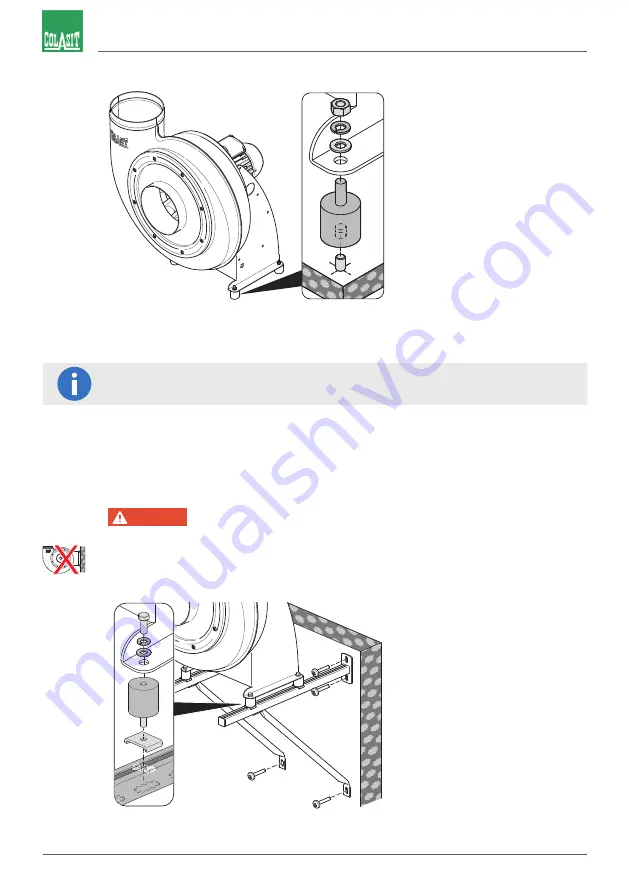
Fig. 23:
Fastening recommendation for floor mounting
1. Transfer fan support hole pattern to the foundation (baseplate).
Hole pattern dimensioning according to technical data sheet.
2. Install anchoring elements (anchors) according to supplier’s instructions.
3. Fix vibration absorbers to anchoring elements.
4. Set fan on vibration absorbers and fasten tightly.
6.6
Wall mounting
DANGER
Risk of injury due to fan falling over
Injuries by pinching and crushing of body parts.
▪ Never mount fan support vertically on the wall!
u
Only mount fan with wall bracket
_
25].
u
Tightly screw in and secure all screw connections.
Conditions:
• Installation location require-
ments
_
30].
• Wall bracket shall be de-
signed for four times the fan
weight.
• Fastening elements
present.
Fig. 24:
Fastening recommendation for wall mounting