


General Information Continued:
To properly service and maintain this vehicle, it is necessary to understand the electrical circuitry and the
functions of all the electrical components. On any PowerDrive System 48 vehicle, there are four separate cir-
cuits in operation: 1) the control circuit, 2) the speed control circuit, 3) the power circuit, and 4) the charge
circuit. A reverse buzzer is also included on every vehicle (See Page 17-29). When working on the electrical
system, refer to the appropriate electrical wiring diagram (Figures 17-2 and 17-3, Pages 17-3 and 17-4) for
more detailed information.
THE ON-BOARD COMPUTER (OBC)
Each PowerDrive System 48 vehicle is equipped with an on-board computer (OBC). The primary function of
the on-board computer is to control the battery charger. By continuously monitoring battery state of charge,
as well as the amount of energy consumed as the vehicle is used, the OBC is able to direct the battery charg-
er to replace exactly the amount of energy needed to replenish the batteries. The OBC uses this data also
to indicate possible battery or charging problems by illuminating a warning light in the dash (For more infor-
mation on the Battery Trouble Light, see Section 19, Page 19-2). OBC data can also be useful in per-
forming electrical system diagnostics. A digital readout of OBC data can be obtained using the Club Car
Communication Display Module (CDM)(Club Car Part No. 1018318-01)(See page 17-22).
The chart in Figure 17-4, Page 17-6 is a quick reference guide to troubleshooting vehicle symptoms that
might be OBC related.
POWERDRIVE VEHICLE ELECTRICAL CIRCUITS
THE CONTROL CIRCUIT
The control circuit consists of the key switch, F&R (Forward and Reverse) anti-arcing limit switch, accelera-
tor limit switch, solenoid, and connecting wires.
17-2
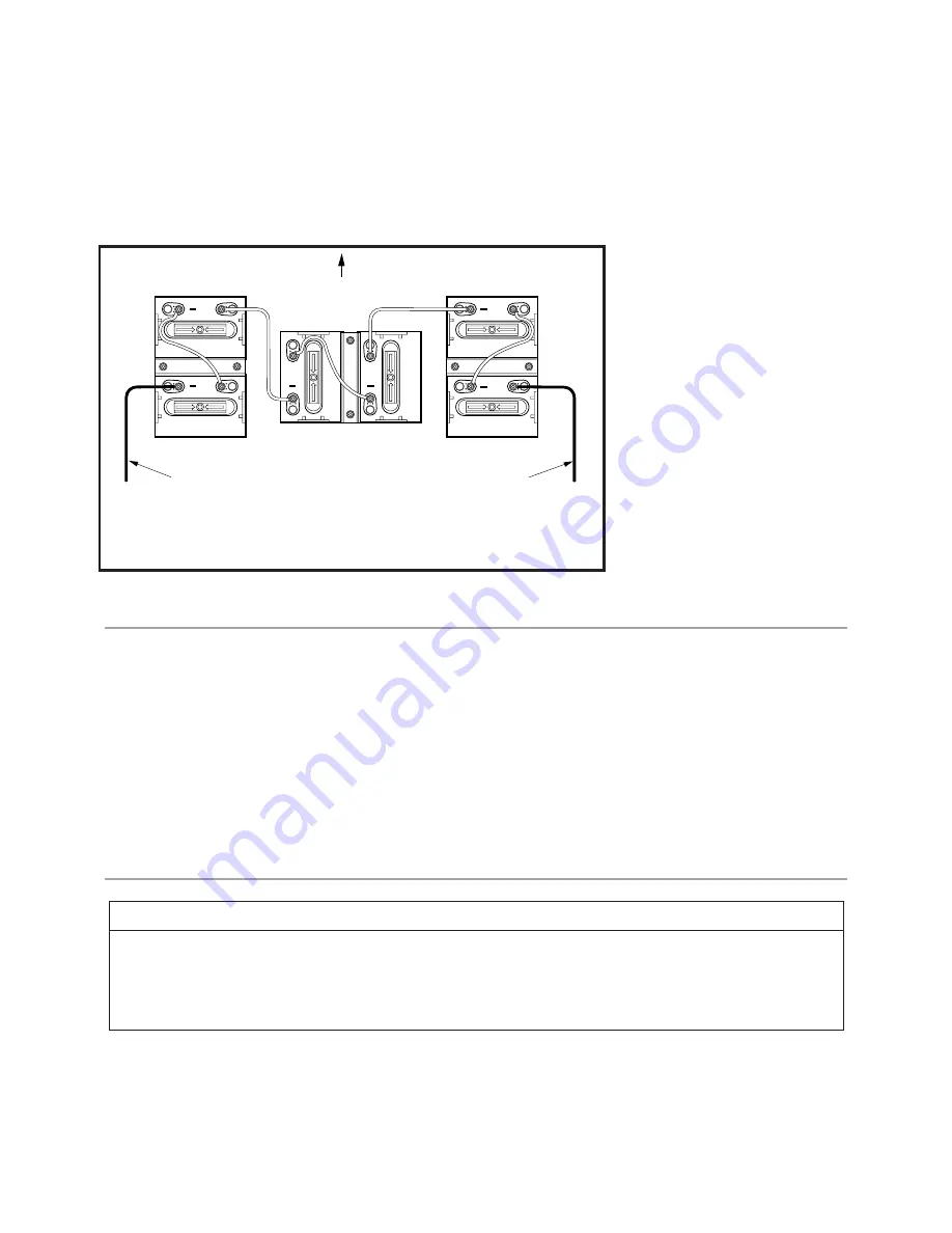
+
+
+
+
+
+
1
2
3
4
5
6
DISCONNECT BLACK
WIRE TO NEGATIVE
TERMINAL
DISCONNECT RED WIRE
TO POSITIVE TERMINAL
FRONT OF VEHICLE
VEHICLE WITH POWERDRIVE SYSTEM 48
FIGURE 17-1
NOTE
• TO SERVICE THE ELECTRICAL SYSTEM, IT IS NECESSARY TO HAVE A CONTINUITY TESTER
OR A VOLT-OHM METER CAPABLE OF READING FROM 0 - 48 VOLTS DC. THE VOM (PART NO.
1011480) AND CONTINUITY TESTER (PART NO. 1011273) ARE AVAILABLE FROM YOUR LOCAL
AUTHORIZED DEALER OR FROM CLUB CAR SERVICE PARTS.
Summary of Contents for 1995 Golf Car
Page 2: ......
Page 44: ......
Page 96: ......
Page 97: ...Club Car R NOTES...
Page 98: ...Club Car R NOTES...
Page 99: ......
Page 100: ......


