


[SMB-66E]
-
55
-
PROGRAM
3
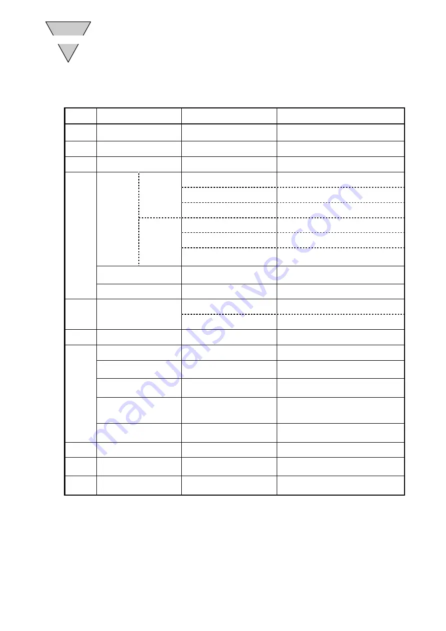
3.3 Code List
1) NC Code
Code
Function
Data Range
Remarks
O
Program number
0 to 999
0 to 255 can be selected from I/O.
"o" is automatically added.
N
Sequence number
0 to 999
Can be omitted.
G
Preparation function
0 to 999
Refer to Section "2) G Code."
A
Instruction to
move
coordinate
axis
G90
,
G91
,
G91.1
±9999999
Unit: pulse
±6658.380
Unit: angle
±4716
Unit: number of indexes
G90.1
,
G90.2
,
G90.3
±540672
Unit: pulse
±360.000
Unit: angle
1 to Designated number of
segments
Unit: number of indexes
Designation of segment
numbers
1 to 255
Continuous rotation speed
±80.00
(Note)
Unit: rpm
F
Designation of speed
0.11 to 300.00
(Note)
Unit: rpm
0.01 to 100.00
Unit: sec
M
Auxiliary function
0 to 99
Refer to Section "3) M Code."
P
Dwell
0.01 to 99.99
Unit: sec
G4P
□□.□□
Designation of sub-program
number
0 to 999
Program No.
M98P
□□□
Gain magnification
0, 50 to 200
Unit: %
G12P
□□□
0% input will set servo-off.
Acceleration and
deceleration for continuous
rotation
0.01 to 50
Unit: sec
G8P
□□□
G9P
□□□
Parameter data setting
Range defined by parameters
Unit: the unit defined by each parameter;
G79S
□□
P
□□□
L
Numbers of repetition
1 to 999
Repeats the block as specified.
J
Jump
0 to 999
J0 causes a return to the top of the
program.
S
Parameter data setting
1 to 99
Setting parameter No.;
G79S
□□
P
□□□
Note : The minimum rotation speed of the actuator is 0.11rpm.
The rotation speed varies among models.
For details, refer to "ACTUATOR SPECIFICATIONS" in the driver instruction manual.
Summary of Contents for AX0180
Page 60: ...SMB 66E 52 OPERATION 2 MEMO...
Page 88: ...SMB 66E 80 PROCESS FLOW 7 MEMO...
Page 94: ...SMB 66E 86 PROCESS FLOW 7 MEMO...
Page 102: ...SMB 66E 94 PROCESS FLOW 7 MEMO...


