12-8
Cisco Wireless LAN Controller Configuration Guide
OL-17037-01
Chapter 12 Configuring Mobility GroupsWireless Device Access
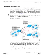
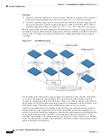
Overview of Mobility Groups
Using Mobility Groups with NAT Devices
In controller software releases prior to 4.2, mobility between controllers in the same mobility group does
not work if one of the controllers is behind a network address translation (NAT) device. This behavior
creates a problem for the guest anchor feature where one controller is expected to be outside the firewall.
Mobility message payloads carry IP address information about the source controller. This IP address is
validated with the source IP address of the IP header. This behavior poses a problem when a NAT device
is introduced in the network because it changes the source IP address in the IP header. Hence, in the guest
WLAN feature, any mobility packet being routed through a NAT device is dropped because of the IP
address mismatch.
In controller software release 4.2 or later, the mobility group lookup is changed to use the MAC address
of the source controller. Because the source IP address is changed due to the mapping in the NAT device,
the mobility group database is searched before a reply is sent to get the IP address of the requesting
controller. This is done using the MAC address of the requesting controller.
When configuring the mobility group in a network where NAT is enabled, enter the IP address sent to
the controller from the NAT device rather than the controller’s management interface IP address. Also,
make sure that the following ports are open on the firewall if you are using a firewall such as PIX:
•
UDP 16666 for tunnel control traffic
•
IP protocol 97 for user data traffic
•
UDP 161 and 162 for SNMP
Note
Client mobility among controllers works only if auto-anchor mobility (also called
guest
tunneling
) or
symmetric mobility tunneling is enabled. Asymmetric tunneling is not supported when mobility
controllers are behind the NAT device. See the
“Configuring Auto-Anchor Mobility”
sections for details on these mobility options.
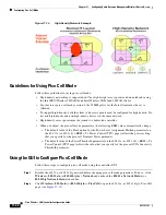
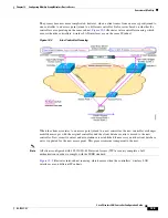
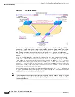
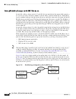
shows an example mobility group configuration with a NAT device. In this example, all
packets pass through the NAT device (that is, packets from the source to the destination and vice versa).
shows an example mobility group configuration with two NAT devices. In this example, one
NAT device is used between the source and the gateway, and the second NAT device is used between the
destination and the gateway.
Figure 12-6
Mobility Group Configuration with One NAT Device
NAT
Anchor controller
(9.x.x.1)
Mobility group
9.x.x.2
Foreign controller
(10.x.x.1)
Mobility group
(10.x.x.2)
232319
10.x.x.2
9.x.x.2

