


35
ENGLISH
EN
structure must be designed to withstand the weight of the
exchanger when in operation (filled) and with its accessories.
• If necessary, affix the hazard symbol corresponding to the
fluid in accordance with applicable standards.
• Take all appropriate steps to mitigate the effects of any signifi-
cant human, environmental or financial consequences of failure.
• Make sure that the heat exchanger is always installed verti-
cally, stable, and secured using all its anchorage points. If
necessary, fit additional anchors suitable for the foreseeable
stresses.
• Install drains and vents, shut-off valves, and fill and drain
valves on the pipes so that the heat exchanger can be ser-
viced without disrupting the system.
• In the event of seasonal use, drain the heat exchanger com-
pletely to prevent any risk of freezing or corrosion if a cor-
rosive fluid is used.
• If accessories are installed on the heat exchanger, refer to
their specific instructions.
3.3 - Hydraulic connections
• To keep the insides of the pipes clean, do not remove the
seals on their ends until you are ready to make the hydraulic
connections.
• The insides of the pipes must be free of all foreign matter
(sand, welding slag, other solid matter, etc.) that could dam-
age the plates and gaskets.
• Filtration: If the fluids to be circulated through the heat ex-
changer contain suspended matter, a filtration system of up
to 500 µm must be installed.
• Check the tightening dimension specified on the nameplate.
Refer to section 5.7 if retightening is needed.
• Make the hydraulic connections as instructed on the name-
plate on the frame or on the plate arrangement drawing.
• Never insert foreign matter into the circuit.
• No strain should be placed on the pipes (weight of connect-
ed pipes, expansion, vibrations etc.).
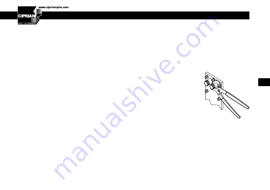
• If threaded couplings are used, do not apply the tightening
torque to the threaded nozzles.
• Threaded nozzles are not weld-
ed to the fixed head. To avoid
damaging the first gasket, hold
the threaded nozzles in place
with pliers and screw on the
pipes (Fig. 4).
• If the ports on the fixed head
are fitted with protective built-in
linings, the linings must be suf-
ficiently compressed so that the
head and the counter-flange are
separated by a 2 mm gap (tightening any further will dam-
age the linings).
• In the case of a multi-pass heat exchanger (fluid inlet and
outlet ports on both ends): install an expansion fitting or a
horseshoe loop and use detachable pipes so that more plates
can be added and the movable follower can be removed.
Fig.4
Summary of Contents for S020+
Page 124: ...124 1 2 60 C CIPRIANI CIPRIANI PED 2014 68 PED 2014 68 CIPRIANI...
Page 125: ...125 RU CIPRIANI...
Page 126: ...126 0 C CIPRIANI CIPRIANI 1 1b 2...
Page 127: ...127 RU 1a 1b 2...
Page 128: ...128 1 2 3 4 5 6 7 8 9 10 11 12...
Page 129: ...129 RU TS PS PT PED 2014 68 CE PED 2014 68 I II III IV CE II III IV 1 2 d d...
Page 131: ...131 RU 60 C 0 C 60 C 500 5 7 4 2 4...
Page 132: ...132 TF PB...
Page 133: ...133 RU CIPRIANI 10...
Page 134: ...134 1 2 3 4 1 2 3 4 4 1 5 CIPRIANI 1 2 3 4 11 5 6 Plug In...
Page 136: ...136 1 2 40 C 3 4...
Page 138: ...138 CIPRIANI 6 Plug In 7 Plug In Plug In 8 Plug In 5 7 1 A 7 6...
Page 139: ...139 RU Plug In 9 b 5 7 3 Plug In Plug In 9 5 7 3 Plug In 5 7 1 Plug In DN200 2 3 5 2 ACS 8 9...
Page 140: ...140 10 11 CIPRIANI PS 10 Fig 10 Fig 11...
Page 144: ...144 CIPRIANI CIPRIANI...
Page 145: ...145 RU CIPRIANI NBR EPDM FPM HNBR...
Page 146: ...146 Note...
Page 147: ...147 Note...