


TEST 2
Test 2 checks the antenna for an open circuit as
follows:
(1) Unplug the antenna coaxial cable connector
from the radio chassis.
(2) Connect one ohmmeter test lead to the tip of
the antenna mast. Connect the other test lead to the
center pin of the antenna coaxial cable connector.
(3) Continuity should exist (the ohmmeter should
only register a fraction of an ohm). High or infinite
resistance indicates damage to the base and cable
assembly. Replace the faulty base and cable, if
required.
TEST 3
Test 3 checks the condition of the vehicle body
ground connection. This test should be performed
with the battery positive cable removed from the bat-
tery. Disconnect both battery cables, the negative
cable first. Reconnect the battery negative cable and
perform the test as follows:
(1) Connect one ohmmeter test lead to the vehicle
fender. Connect the other test lead to the battery
negative post.
(2) The resistance should be less than (1) ohm.
(3) If the resistance is more than (1) ohm, check
the braided ground strap connected to the engine and
the vehicle body for being loose, corroded, or dam-
aged. Repair the ground strap connection, if required.
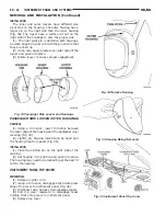
TEST 4
Test 4 checks the condition of the ground between
the antenna base and the vehicle body as follows:
(1) Connect one ohmmeter test lead to the vehicle
fender. Connect the other test lead to the outer crimp
on the antenna coaxial cable connector.
(2) The resistance should be less then (1) ohm.
(3) If the resistance is more then (1) ohm, clean
and/or tighten the antenna base to fender mounting
hardware.
AUDIO SYSTEM
WARNING: ON VEHICLES EQUIPPED WITH AIR-
BAGS,
REFER
TO
GROUP
8M
-
PASSIVE
RESTRAINT SYSTEMS BEFORE ATTEMPTING ANY
STEERING
WHEEL,
STEERING
COLUMN,
OR
INSTRUMENT PANEL COMPONENT DIAGNOSIS OR
SERVICE. FAILURE TO TAKE THE PROPER PRE-
CAUTIONS COULD RESULT IN ACCIDENTAL AIR-
BAG DEPLOYMENT AND POSSIBLE PERSONAL
INJURY.
RADIO
If the vehicle is equipped with remote radio
switches located on the backs of the steering wheel
spokes, and the problem being diagnosed is related to
one of the symptoms listed below, be certain to check
the remote radio switches and circuits as described
in this group, prior to attempting radio diagnosis or
repair.
•
Stations changing with no remote radio switch
input
•
Radio memory presets not working properly
•
Volume changes with no remote radio switch
input
•
Remote radio switch buttons taking on other
functions
•
CD player skipping tracks
•
Remote radio switch inoperative.
For circuit descriptions and diagrams, refer to
Group 8W - Wiring Diagrams.
WARNING: ON VEHICLES EQUIPPED WITH AIR-
BAGS,
REFER
TO
GROUP
8M
-
PASSIVE
RESTRAINT SYSTEMS BEFORE ATTEMPTING ANY
STEERING
WHEEL,
STEERING
COLUMN,
OR
INSTRUMENT PANEL COMPONENT DIAGNOSIS OR
SERVICE. FAILURE TO TAKE THE PROPER PRE-
CAUTIONS COULD RESULT IN ACCIDENTAL AIR-
BAG DEPLOYMENT AND POSSIBLE PERSONAL
INJURY.
CAUTION: The speaker output of the radio is a
“floating ground” system. Do not allow any speaker
lead to short to ground, as damage to the radio
may result.
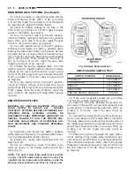
Fig. 7 Antenna Tests
8F - 4
AUDIO SYSTEMS
NS
DIAGNOSIS AND TESTING (Continued)
Summary of Contents for 1998 Voyager
Page 8: ...FASTENER IDENTIFICATION NS INTRODUCTION 5 GENERAL INFORMATION Continued ...
Page 9: ...FASTENER STRENGTH 6 INTRODUCTION NS GENERAL INFORMATION Continued ...
Page 11: ...METRIC CONVERSION 8 INTRODUCTION NS GENERAL INFORMATION Continued ...
Page 12: ...TORQUE SPECIFICATIONS NS INTRODUCTION 9 GENERAL INFORMATION Continued ...
Page 16: ......
Page 26: ......
Page 93: ...RED BRAKE WARNING LAMP FUNCTION NS BRAKES 5 11 DIAGNOSIS AND TESTING Continued ...
Page 94: ...POWER BRAKE SYSTEM DIAGNOSTICS 5 12 BRAKES NS DIAGNOSIS AND TESTING Continued ...
Page 95: ...VEHICLE ROAD TEST BRAKE NOISE NS BRAKES 5 13 DIAGNOSIS AND TESTING Continued ...
Page 222: ...COOLING SYSTEM DIAGNOSIS 7 8 COOLING SYSTEM NS DIAGNOSIS AND TESTING Continued ...
Page 223: ...NS COOLING SYSTEM 7 9 DIAGNOSIS AND TESTING Continued ...
Page 224: ...7 10 COOLING SYSTEM NS DIAGNOSIS AND TESTING Continued ...
Page 225: ...NS COOLING SYSTEM 7 11 DIAGNOSIS AND TESTING Continued ...
Page 226: ...7 12 COOLING SYSTEM NS DIAGNOSIS AND TESTING Continued ...
Page 280: ......
Page 286: ......
Page 289: ...CHARGING SYSTEM SCHEMATIC TYPICAL NS CHARGING SYSTEM 8C 3 DIAGNOSIS AND TESTING Continued ...
Page 291: ...CHARGING SYSTEM TEST NS CHARGING SYSTEM 8C 5 DIAGNOSIS AND TESTING Continued ...
Page 292: ...OVERCHARGE TEST 8C 6 CHARGING SYSTEM NS DIAGNOSIS AND TESTING Continued ...
Page 294: ...VOLTAGE DROP TEST 8C 8 CHARGING SYSTEM NS ...
Page 298: ......
Page 372: ......
Page 377: ...NS GS INSTRUMENT PANEL AND SYSTEMS 8E 5 DIAGNOSIS AND TESTING Continued ...
Page 378: ...8E 6 INSTRUMENT PANEL AND SYSTEMS NS GS DIAGNOSIS AND TESTING Continued ...
Page 379: ...NS GS INSTRUMENT PANEL AND SYSTEMS 8E 7 DIAGNOSIS AND TESTING Continued ...
Page 380: ...8E 8 INSTRUMENT PANEL AND SYSTEMS NS GS DIAGNOSIS AND TESTING Continued ...
Page 381: ...NS GS INSTRUMENT PANEL AND SYSTEMS 8E 9 DIAGNOSIS AND TESTING Continued ...
Page 382: ...8E 10 INSTRUMENT PANEL AND SYSTEMS NS GS DIAGNOSIS AND TESTING Continued ...
Page 383: ...NS GS INSTRUMENT PANEL AND SYSTEMS 8E 11 DIAGNOSIS AND TESTING Continued ...
Page 384: ...8E 12 INSTRUMENT PANEL AND SYSTEMS NS GS DIAGNOSIS AND TESTING Continued ...
Page 385: ...NS GS INSTRUMENT PANEL AND SYSTEMS 8E 13 DIAGNOSIS AND TESTING Continued ...
Page 386: ...8E 14 INSTRUMENT PANEL AND SYSTEMS NS GS DIAGNOSIS AND TESTING Continued ...
Page 402: ......
Page 428: ......
Page 440: ......
Page 478: ......
Page 496: ......
Page 504: ......
Page 508: ......
Page 524: ......
Page 542: ......
Page 546: ......
Page 550: ......
Page 559: ...SPECIAL TOOLS SPECIAL TOOL Degausser 6029 NS OVERHEAD CONSOLE 8V 9 ...
Page 560: ......
Page 562: ......
Page 564: ...8W 01 2 8W 01 GENERAL INFORMATION NS GS DESCRIPTION AND OPERATION Continued ...
Page 565: ...NS GS 8W 01 GENERAL INFORMATION 8W 01 3 DESCRIPTION AND OPERATION Continued ...
Page 580: ......
Page 616: ......
Page 660: ......
Page 664: ......
Page 704: ......
Page 718: ......
Page 728: ......
Page 740: ......
Page 744: ......
Page 758: ......
Page 768: ......
Page 784: ......
Page 792: ......
Page 796: ......
Page 800: ......
Page 814: ......
Page 822: ......
Page 826: ......
Page 832: ......
Page 836: ......
Page 840: ......
Page 876: ......
Page 1024: ......
Page 1220: ...Fig 3 Lubrication Lines 9 42 ENGINE NS GS DESCRIPTION AND OPERATION Continued ...
Page 1224: ...ENGINE DIAGNOSIS MECHANICAL CONT 9 46 ENGINE NS GS DIAGNOSIS AND TESTING Continued ...
Page 1286: ...Fig 5 Front Crossmember Dimensions 13 6 FRAME AND BUMPERS NS SPECIFICATIONS Continued ...
Page 1287: ...Fig 6 Engine Compartment Top View NS FRAME AND BUMPERS 13 7 SPECIFICATIONS Continued ...
Page 1289: ...Fig 8 Full Vehicle Bottom View NS FRAME AND BUMPERS 13 9 SPECIFICATIONS Continued ...
Page 1291: ...Fig 11 Body Side Openings NS FRAME AND BUMPERS 13 11 SPECIFICATIONS Continued ...
Page 1292: ......
Page 1302: ...FUEL PRESSURE BELOW SPECIFICATIONS 14 8 FUEL SYSTEM NS DIAGNOSIS AND TESTING Continued ...
Page 1304: ...FUEL INJECTOR DIAGNOSIS 14 10 FUEL SYSTEM NS DIAGNOSIS AND TESTING Continued ...
Page 1368: ......
Page 1426: ......
Page 1472: ......
Page 1479: ...Diagnosis Guide NS TRANSAXLE AND POWER TRANSFER UNIT 21 5 DIAGNOSIS AND TESTING Continued ...
Page 1480: ...Diagnosis Guide 21 6 TRANSAXLE AND POWER TRANSFER UNIT NS DIAGNOSIS AND TESTING Continued ...
Page 1481: ...Diagnosis Guide NS TRANSAXLE AND POWER TRANSFER UNIT 21 7 DIAGNOSIS AND TESTING Continued ...
Page 1482: ...Diagnosis Guide 21 8 TRANSAXLE AND POWER TRANSFER UNIT NS DIAGNOSIS AND TESTING Continued ...
Page 1483: ...Diagnosis Guide NS TRANSAXLE AND POWER TRANSFER UNIT 21 9 DIAGNOSIS AND TESTING Continued ...
Page 1484: ...Diagnosis Guide 21 10 TRANSAXLE AND POWER TRANSFER UNIT NS DIAGNOSIS AND TESTING Continued ...
Page 1485: ...Diagnosis Guide NS TRANSAXLE AND POWER TRANSFER UNIT 21 11 DIAGNOSIS AND TESTING Continued ...
Page 1486: ...Diagnosis Guide 21 12 TRANSAXLE AND POWER TRANSFER UNIT NS DIAGNOSIS AND TESTING Continued ...
Page 1656: ......
Page 1723: ...LEAD CORRECTION CHART NS TIRES AND WHEELS 22 5 DIAGNOSIS AND TESTING Continued ...
Page 1726: ...SPECIFICATIONS TIRE SPECIFICATIONS 22 8 TIRES AND WHEELS NS ...
Page 1866: ......
Page 1904: ......
Page 1928: ......