


leaks are not present. The component should be
replaced immediately if there is any evidence of deg-
radation that could result in failure.
Never attempt to repair a plastic fuel line/tube or a
quick–connect fitting. Replace complete line/tube as
necessary.
Avoid contact of any fuel tubes/hoses with other
vehicle components that could cause abrasions or
scuffing. Be sure that the fuel lines/tubes are prop-
erly routed to prevent pinching and to avoid heat
sources.
The lines/tubes/hoses are of a special construction.
If it is necessary to replace these lines/tubes/hoses,
use only original equipment type.
The hose clamps used to secure the rubber hoses
are of a special rolled edge construction. This con-
struction is used to prevent the edge of the clamp
from cutting into the hose. Only these rolled edge
type clamps may be used in this system. All other
types of clamps may cut into the hoses and cause
fuel leaks.
Where a rubber hose is joined to a metal tube
(staked), do not attempt to repair. Replace entire
line/tube assembly.
Use new original equipment type hose clamps.
Tighten hose clamps to 2 N·m (20 in. lbs.) torque.
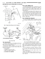
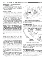
QUICK-CONNECT FITTINGS—LOW PRESSURE
TYPE
Different types of quick-connect fittings are used to
attach various fuel system components. These are: a
single-tab type, a two-tab type or a plastic retainer
ring type (Fig. 8). Refer to Quick-Connect Fittings in
the Removal/Installation section for more informa-
tion.
CAUTION:
The interior components (o-rings, spac-
ers) of quick-connect fitting are not serviced sepa-
rately, but new pull tabs are available for some
types. Do not attempt to repair damaged fittings or
fuel lines/tubes. If repair is necessary, replace the
complete fuel tube assembly.
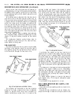
HIGH-PRESSURE FUEL LINES
CAUTION: The high–pressure fuel lines must be
held securely in place in their holders. The lines
cannot contact each other or other components. Do
not attempt to weld high–pressure fuel lines or to
repair lines that are damaged. Only use the recom-
mended lines when replacement of high–pressure
fuel line is necessary.
High–pressure fuel lines deliver fuel under pres-
sure of up to approximately 45,000 kPa (6526 PSI)
from the injection pump to the fuel injectors. The
lines expand and contract from the high–pressure
fuel pulses generated during the injection process. All
high–pressure fuel lines are of the same length and
inside diameter. Correct high–pressure fuel line
usage and installation is critical to smooth engine
operation.
WARNING: USE
EXTREME
CAUTION
WHEN
INSPECTING FOR HIGH–PRESSURE FUEL LEAKS.
INSPECT FOR HIGH–PRESSURE FUEL LEAKS WITH
A SHEET OF CARDBOARD. HIGH FUEL INJECTION
PRESSURE CAN CAUSE PERSONAL INJURY IF
CONTACT IS MADE WITH THE SKIN.
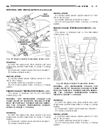
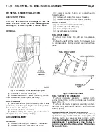
FUEL DRAIN TUBES
These rubber tubes are low–pressure type.
Some excess fuel is continually vented from the
fuel injection pump. During injection, a small amount
of fuel flows past the injector nozzle and is not
injected into the combustion chamber. This fuel
drains into the fuel drain tubes (Fig. 9) and back to
the tee banjo fitting, which is connected to the same
line as the overflow valve, which allows a variable
quantity to return to the fuel tank. The overflow
valve is calibrated to open at a preset pressure.
Excess fuel not required by the pump to maintain the
minimum pump cavity pressure is then returned
through the overflow valve and on to the fuel tank
through the fuel return line.
Fig. 8 Plastic Retainer Ring-Type Fitting
NS/GS
FUEL SYSTEM—2.5L DIESEL ENGINE/2.0L GAS ENGINE
14 - 7
DESCRIPTION AND OPERATION (Continued)
Summary of Contents for 1998 Voyager
Page 8: ...FASTENER IDENTIFICATION NS INTRODUCTION 5 GENERAL INFORMATION Continued ...
Page 9: ...FASTENER STRENGTH 6 INTRODUCTION NS GENERAL INFORMATION Continued ...
Page 11: ...METRIC CONVERSION 8 INTRODUCTION NS GENERAL INFORMATION Continued ...
Page 12: ...TORQUE SPECIFICATIONS NS INTRODUCTION 9 GENERAL INFORMATION Continued ...
Page 16: ......
Page 26: ......
Page 93: ...RED BRAKE WARNING LAMP FUNCTION NS BRAKES 5 11 DIAGNOSIS AND TESTING Continued ...
Page 94: ...POWER BRAKE SYSTEM DIAGNOSTICS 5 12 BRAKES NS DIAGNOSIS AND TESTING Continued ...
Page 95: ...VEHICLE ROAD TEST BRAKE NOISE NS BRAKES 5 13 DIAGNOSIS AND TESTING Continued ...
Page 222: ...COOLING SYSTEM DIAGNOSIS 7 8 COOLING SYSTEM NS DIAGNOSIS AND TESTING Continued ...
Page 223: ...NS COOLING SYSTEM 7 9 DIAGNOSIS AND TESTING Continued ...
Page 224: ...7 10 COOLING SYSTEM NS DIAGNOSIS AND TESTING Continued ...
Page 225: ...NS COOLING SYSTEM 7 11 DIAGNOSIS AND TESTING Continued ...
Page 226: ...7 12 COOLING SYSTEM NS DIAGNOSIS AND TESTING Continued ...
Page 280: ......
Page 286: ......
Page 289: ...CHARGING SYSTEM SCHEMATIC TYPICAL NS CHARGING SYSTEM 8C 3 DIAGNOSIS AND TESTING Continued ...
Page 291: ...CHARGING SYSTEM TEST NS CHARGING SYSTEM 8C 5 DIAGNOSIS AND TESTING Continued ...
Page 292: ...OVERCHARGE TEST 8C 6 CHARGING SYSTEM NS DIAGNOSIS AND TESTING Continued ...
Page 294: ...VOLTAGE DROP TEST 8C 8 CHARGING SYSTEM NS ...
Page 298: ......
Page 372: ......
Page 377: ...NS GS INSTRUMENT PANEL AND SYSTEMS 8E 5 DIAGNOSIS AND TESTING Continued ...
Page 378: ...8E 6 INSTRUMENT PANEL AND SYSTEMS NS GS DIAGNOSIS AND TESTING Continued ...
Page 379: ...NS GS INSTRUMENT PANEL AND SYSTEMS 8E 7 DIAGNOSIS AND TESTING Continued ...
Page 380: ...8E 8 INSTRUMENT PANEL AND SYSTEMS NS GS DIAGNOSIS AND TESTING Continued ...
Page 381: ...NS GS INSTRUMENT PANEL AND SYSTEMS 8E 9 DIAGNOSIS AND TESTING Continued ...
Page 382: ...8E 10 INSTRUMENT PANEL AND SYSTEMS NS GS DIAGNOSIS AND TESTING Continued ...
Page 383: ...NS GS INSTRUMENT PANEL AND SYSTEMS 8E 11 DIAGNOSIS AND TESTING Continued ...
Page 384: ...8E 12 INSTRUMENT PANEL AND SYSTEMS NS GS DIAGNOSIS AND TESTING Continued ...
Page 385: ...NS GS INSTRUMENT PANEL AND SYSTEMS 8E 13 DIAGNOSIS AND TESTING Continued ...
Page 386: ...8E 14 INSTRUMENT PANEL AND SYSTEMS NS GS DIAGNOSIS AND TESTING Continued ...
Page 402: ......
Page 428: ......
Page 440: ......
Page 478: ......
Page 496: ......
Page 504: ......
Page 508: ......
Page 524: ......
Page 542: ......
Page 546: ......
Page 550: ......
Page 559: ...SPECIAL TOOLS SPECIAL TOOL Degausser 6029 NS OVERHEAD CONSOLE 8V 9 ...
Page 560: ......
Page 562: ......
Page 564: ...8W 01 2 8W 01 GENERAL INFORMATION NS GS DESCRIPTION AND OPERATION Continued ...
Page 565: ...NS GS 8W 01 GENERAL INFORMATION 8W 01 3 DESCRIPTION AND OPERATION Continued ...
Page 580: ......
Page 616: ......
Page 660: ......
Page 664: ......
Page 704: ......
Page 718: ......
Page 728: ......
Page 740: ......
Page 744: ......
Page 758: ......
Page 768: ......
Page 784: ......
Page 792: ......
Page 796: ......
Page 800: ......
Page 814: ......
Page 822: ......
Page 826: ......
Page 832: ......
Page 836: ......
Page 840: ......
Page 876: ......
Page 1024: ......
Page 1220: ...Fig 3 Lubrication Lines 9 42 ENGINE NS GS DESCRIPTION AND OPERATION Continued ...
Page 1224: ...ENGINE DIAGNOSIS MECHANICAL CONT 9 46 ENGINE NS GS DIAGNOSIS AND TESTING Continued ...
Page 1286: ...Fig 5 Front Crossmember Dimensions 13 6 FRAME AND BUMPERS NS SPECIFICATIONS Continued ...
Page 1287: ...Fig 6 Engine Compartment Top View NS FRAME AND BUMPERS 13 7 SPECIFICATIONS Continued ...
Page 1289: ...Fig 8 Full Vehicle Bottom View NS FRAME AND BUMPERS 13 9 SPECIFICATIONS Continued ...
Page 1291: ...Fig 11 Body Side Openings NS FRAME AND BUMPERS 13 11 SPECIFICATIONS Continued ...
Page 1292: ......
Page 1302: ...FUEL PRESSURE BELOW SPECIFICATIONS 14 8 FUEL SYSTEM NS DIAGNOSIS AND TESTING Continued ...
Page 1304: ...FUEL INJECTOR DIAGNOSIS 14 10 FUEL SYSTEM NS DIAGNOSIS AND TESTING Continued ...
Page 1368: ......
Page 1426: ......
Page 1472: ......
Page 1479: ...Diagnosis Guide NS TRANSAXLE AND POWER TRANSFER UNIT 21 5 DIAGNOSIS AND TESTING Continued ...
Page 1480: ...Diagnosis Guide 21 6 TRANSAXLE AND POWER TRANSFER UNIT NS DIAGNOSIS AND TESTING Continued ...
Page 1481: ...Diagnosis Guide NS TRANSAXLE AND POWER TRANSFER UNIT 21 7 DIAGNOSIS AND TESTING Continued ...
Page 1482: ...Diagnosis Guide 21 8 TRANSAXLE AND POWER TRANSFER UNIT NS DIAGNOSIS AND TESTING Continued ...
Page 1483: ...Diagnosis Guide NS TRANSAXLE AND POWER TRANSFER UNIT 21 9 DIAGNOSIS AND TESTING Continued ...
Page 1484: ...Diagnosis Guide 21 10 TRANSAXLE AND POWER TRANSFER UNIT NS DIAGNOSIS AND TESTING Continued ...
Page 1485: ...Diagnosis Guide NS TRANSAXLE AND POWER TRANSFER UNIT 21 11 DIAGNOSIS AND TESTING Continued ...
Page 1486: ...Diagnosis Guide 21 12 TRANSAXLE AND POWER TRANSFER UNIT NS DIAGNOSIS AND TESTING Continued ...
Page 1656: ......
Page 1723: ...LEAD CORRECTION CHART NS TIRES AND WHEELS 22 5 DIAGNOSIS AND TESTING Continued ...
Page 1726: ...SPECIFICATIONS TIRE SPECIFICATIONS 22 8 TIRES AND WHEELS NS ...
Page 1866: ......
Page 1904: ......
Page 1928: ......