


The speed sensor generates 8 pulses per sensor
revolution. These signals, in conjunction with a
closed throttle signal from the throttle position sen-
sor, indicate a closed throttle deceleration to the
PCM. When the vehicle is stopped at idle, a closed
throttle signal is received by the PCM (but a speed
sensor signal is not received).
In addition to determining distance and vehicle
speed, the output from the sensor is used to control
speed control operation.
SPEED CONTROL—PCM INPUTS
The speed control system provides five separate
inputs to the PCM; On/Off, Set, Resume/Accel, Cancel,
and Decel.. The On/Off input informs the PCM that
the speed control system has been activated. The Set
input informs the PCM that a fixed vehicle speed has
been selected. The Resume input indicates to the PCM
that the previous fixed speed is requested.
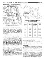
Speed control operation will start at 50 km/h–142
km/h (35–85 mph). The upper range of operation is
not restricted by vehicle speed. Inputs that affect
speed control operation are vehicle speed sensor and
throttle position sensor.
Refer to Group 8H for further speed control infor-
mation.
DIESEL PCM RELAY—PCM INPUT
A 12 volt signal at this input indicates to the PCM
that the Diesel relay has been activated. The Diesel
relay is located in the PDC. The PDC is located next
to the battery in the engine compartment. For the
location of the relay within the PDC, refer to label on
PDC cover.
This input is used only to sense that the Diesel
relay is energized. If the PCM does not see 12 volts +
at this input when the Diesel relay should be acti-
vated, it will set a Diagnostic Trouble Code (DTC).
FIVE VOLT POWER—PCM OUTPUT
This circuit supplies approximately 5 volts to
power the Accelerator Pedal Postion Sensor, Mass Air
Flow Sensor, and A/C Pressure Sensor.
ENGINE COOLANT GAUGE—PCM OUTPUT
Refer to the Instrument Panel and Gauges group
for additional information.
ENGINE OIL PRESSURE GAUGE—PCM OUTPUT
Refer to the Instrument Panel and Gauges group
for additional information.
GLOW PLUG LAMP—PCM OUTPUT
The Glow Plug lamp (malfunction indicator lamp)
illuminates on the message center each time the igni-
tion (key) switch is turned on. It will stay on for
about two seconds as a bulb test.
If the PCM receives an incorrect signal, or no sig-
nal from certain sensors or components, the lamp
BLINKS. This is a warning that the PCM has
recorded a system or sensor malfunction. It signals
an immediate need for service. There are only 5
HARD faults that can turn on this lamp to make it
blink.
SPEED CONTROL—PCM OUTPUTS
These two circuits control the fuel quantity actua-
tor to regulate vehicle speed. Refer to Group 8H for
Speed Control information.
AIR CONDITIONING RELAY—PCM OUTPUT
This circuit controls a ground signal for operation
of the A/C clutch relay. Also refer to Air Conditioning
(A/C) Controls—PCM Input for additional informa-
tion.
The A/C relay is located in the Power Distribution
Center (PDC). The PDC is located next to the battery
in the engine compartment. For the location of the
relay within the PDC, refer to label on PDC cover.
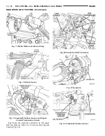
FUEL TIMING SOLENOID—PCM OUTPUT
The fuel timing solenoid is located on the bottom of
the fuel injection pump (Fig. 10).
This 12+ volt, pulse width modulated (duty–cycle)
output controls the amount of fuel timing (advance)
in the fuel injection pump. The higher the duty-
Fig. 9 Glow Plug Lamp Symbol
Fig. 10 Fuel Timing Solenoid
14 - 48
FUEL SYSTEM—2.5L DIESEL ENGINE/2.0L GAS ENGINE
NS/GS
DESCRIPTION AND OPERATION (Continued)
Summary of Contents for 1998 Voyager
Page 8: ...FASTENER IDENTIFICATION NS INTRODUCTION 5 GENERAL INFORMATION Continued ...
Page 9: ...FASTENER STRENGTH 6 INTRODUCTION NS GENERAL INFORMATION Continued ...
Page 11: ...METRIC CONVERSION 8 INTRODUCTION NS GENERAL INFORMATION Continued ...
Page 12: ...TORQUE SPECIFICATIONS NS INTRODUCTION 9 GENERAL INFORMATION Continued ...
Page 16: ......
Page 26: ......
Page 93: ...RED BRAKE WARNING LAMP FUNCTION NS BRAKES 5 11 DIAGNOSIS AND TESTING Continued ...
Page 94: ...POWER BRAKE SYSTEM DIAGNOSTICS 5 12 BRAKES NS DIAGNOSIS AND TESTING Continued ...
Page 95: ...VEHICLE ROAD TEST BRAKE NOISE NS BRAKES 5 13 DIAGNOSIS AND TESTING Continued ...
Page 222: ...COOLING SYSTEM DIAGNOSIS 7 8 COOLING SYSTEM NS DIAGNOSIS AND TESTING Continued ...
Page 223: ...NS COOLING SYSTEM 7 9 DIAGNOSIS AND TESTING Continued ...
Page 224: ...7 10 COOLING SYSTEM NS DIAGNOSIS AND TESTING Continued ...
Page 225: ...NS COOLING SYSTEM 7 11 DIAGNOSIS AND TESTING Continued ...
Page 226: ...7 12 COOLING SYSTEM NS DIAGNOSIS AND TESTING Continued ...
Page 280: ......
Page 286: ......
Page 289: ...CHARGING SYSTEM SCHEMATIC TYPICAL NS CHARGING SYSTEM 8C 3 DIAGNOSIS AND TESTING Continued ...
Page 291: ...CHARGING SYSTEM TEST NS CHARGING SYSTEM 8C 5 DIAGNOSIS AND TESTING Continued ...
Page 292: ...OVERCHARGE TEST 8C 6 CHARGING SYSTEM NS DIAGNOSIS AND TESTING Continued ...
Page 294: ...VOLTAGE DROP TEST 8C 8 CHARGING SYSTEM NS ...
Page 298: ......
Page 372: ......
Page 377: ...NS GS INSTRUMENT PANEL AND SYSTEMS 8E 5 DIAGNOSIS AND TESTING Continued ...
Page 378: ...8E 6 INSTRUMENT PANEL AND SYSTEMS NS GS DIAGNOSIS AND TESTING Continued ...
Page 379: ...NS GS INSTRUMENT PANEL AND SYSTEMS 8E 7 DIAGNOSIS AND TESTING Continued ...
Page 380: ...8E 8 INSTRUMENT PANEL AND SYSTEMS NS GS DIAGNOSIS AND TESTING Continued ...
Page 381: ...NS GS INSTRUMENT PANEL AND SYSTEMS 8E 9 DIAGNOSIS AND TESTING Continued ...
Page 382: ...8E 10 INSTRUMENT PANEL AND SYSTEMS NS GS DIAGNOSIS AND TESTING Continued ...
Page 383: ...NS GS INSTRUMENT PANEL AND SYSTEMS 8E 11 DIAGNOSIS AND TESTING Continued ...
Page 384: ...8E 12 INSTRUMENT PANEL AND SYSTEMS NS GS DIAGNOSIS AND TESTING Continued ...
Page 385: ...NS GS INSTRUMENT PANEL AND SYSTEMS 8E 13 DIAGNOSIS AND TESTING Continued ...
Page 386: ...8E 14 INSTRUMENT PANEL AND SYSTEMS NS GS DIAGNOSIS AND TESTING Continued ...
Page 402: ......
Page 428: ......
Page 440: ......
Page 478: ......
Page 496: ......
Page 504: ......
Page 508: ......
Page 524: ......
Page 542: ......
Page 546: ......
Page 550: ......
Page 559: ...SPECIAL TOOLS SPECIAL TOOL Degausser 6029 NS OVERHEAD CONSOLE 8V 9 ...
Page 560: ......
Page 562: ......
Page 564: ...8W 01 2 8W 01 GENERAL INFORMATION NS GS DESCRIPTION AND OPERATION Continued ...
Page 565: ...NS GS 8W 01 GENERAL INFORMATION 8W 01 3 DESCRIPTION AND OPERATION Continued ...
Page 580: ......
Page 616: ......
Page 660: ......
Page 664: ......
Page 704: ......
Page 718: ......
Page 728: ......
Page 740: ......
Page 744: ......
Page 758: ......
Page 768: ......
Page 784: ......
Page 792: ......
Page 796: ......
Page 800: ......
Page 814: ......
Page 822: ......
Page 826: ......
Page 832: ......
Page 836: ......
Page 840: ......
Page 876: ......
Page 1024: ......
Page 1220: ...Fig 3 Lubrication Lines 9 42 ENGINE NS GS DESCRIPTION AND OPERATION Continued ...
Page 1224: ...ENGINE DIAGNOSIS MECHANICAL CONT 9 46 ENGINE NS GS DIAGNOSIS AND TESTING Continued ...
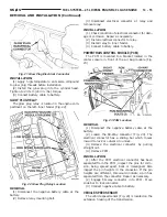
Page 1286: ...Fig 5 Front Crossmember Dimensions 13 6 FRAME AND BUMPERS NS SPECIFICATIONS Continued ...
Page 1287: ...Fig 6 Engine Compartment Top View NS FRAME AND BUMPERS 13 7 SPECIFICATIONS Continued ...
Page 1289: ...Fig 8 Full Vehicle Bottom View NS FRAME AND BUMPERS 13 9 SPECIFICATIONS Continued ...
Page 1291: ...Fig 11 Body Side Openings NS FRAME AND BUMPERS 13 11 SPECIFICATIONS Continued ...
Page 1292: ......
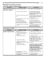
Page 1302: ...FUEL PRESSURE BELOW SPECIFICATIONS 14 8 FUEL SYSTEM NS DIAGNOSIS AND TESTING Continued ...
Page 1304: ...FUEL INJECTOR DIAGNOSIS 14 10 FUEL SYSTEM NS DIAGNOSIS AND TESTING Continued ...
Page 1368: ......
Page 1426: ......
Page 1472: ......
Page 1479: ...Diagnosis Guide NS TRANSAXLE AND POWER TRANSFER UNIT 21 5 DIAGNOSIS AND TESTING Continued ...
Page 1480: ...Diagnosis Guide 21 6 TRANSAXLE AND POWER TRANSFER UNIT NS DIAGNOSIS AND TESTING Continued ...
Page 1481: ...Diagnosis Guide NS TRANSAXLE AND POWER TRANSFER UNIT 21 7 DIAGNOSIS AND TESTING Continued ...
Page 1482: ...Diagnosis Guide 21 8 TRANSAXLE AND POWER TRANSFER UNIT NS DIAGNOSIS AND TESTING Continued ...
Page 1483: ...Diagnosis Guide NS TRANSAXLE AND POWER TRANSFER UNIT 21 9 DIAGNOSIS AND TESTING Continued ...
Page 1484: ...Diagnosis Guide 21 10 TRANSAXLE AND POWER TRANSFER UNIT NS DIAGNOSIS AND TESTING Continued ...
Page 1485: ...Diagnosis Guide NS TRANSAXLE AND POWER TRANSFER UNIT 21 11 DIAGNOSIS AND TESTING Continued ...
Page 1486: ...Diagnosis Guide 21 12 TRANSAXLE AND POWER TRANSFER UNIT NS DIAGNOSIS AND TESTING Continued ...
Page 1656: ......
Page 1723: ...LEAD CORRECTION CHART NS TIRES AND WHEELS 22 5 DIAGNOSIS AND TESTING Continued ...
Page 1726: ...SPECIFICATIONS TIRE SPECIFICATIONS 22 8 TIRES AND WHEELS NS ...
Page 1866: ......
Page 1904: ......
Page 1928: ......