


to Group 8W for wiring connector and circuitry infor-
mation. Repair the wire harness if an open circuit is
indicated.
(4) After tests are completed, connect electrical
connector to sensor.
GLOW PLUG TEST
Hard starting or a rough idle after starting may be
caused by one or more defective glow plugs. Before
testing the glow plugs, a test of the glow plug relay
should be performed. This will ensure that 12V+ is
available at the plugs when starting the engine.
Refer to the Glow Plug Relay Test for information.
For accurate test results, the glow plugs should be
removed from the engine. The plugs must be checked
when cold. Do not check the plugs if the engine
has
recently
been
operated.
If
plugs
are
checked when warm, incorrect amp gauge
readings will result.
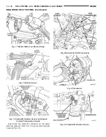
Use Churchill Glow Plug Tester DX.900 or an
equivalent (Fig. 14) for the following tests. This
tester is equipped with 4 timer lamps.
(1) Remove the glow plugs from the engine. Refer
to Glow Plug Removal/Installation.
(2) Attach the red lead of the tester to the 12V+
(positive) side of the battery.
(3) Attach the black lead of the tester to the 12V–
(negative) side of the battery.
(4) Fit the glow plug into the top of the tester and
secure it with the spring loaded bar (Fig. 14).
(5) Attach the third lead wire of the tester to the
electrical terminal at the end of the glow plug.
(6) When performing the test, the tester button
(Fig. 14) should be held continuously without release
for 20 seconds as indicated by the 4 timer lamps.
Each illuminated lamp represents a 5 second time
lapse.
(a) Press and hold the tester button (Fig. 14)
and note the amp gauge reading. The gauge read-
ing should indicate a momentary, initial current
draw (surge) of approximately 25 amps. After the
initial surge, the amp gauge reading should begin
to fall off. The glow plug tip should start to glow
an orange color after 5 seconds. If the tip did not
glow after 5 seconds, replace the glow plug. Before
discarding the glow plug, check the position of the
circuit breaker on the bottom of the plug tester. It
may have to be reset. Reset if necessary.
(b) Continue to hold the tester button while
observing the amp gauge and the 4 timer lamps.
When all 4 lamps are illuminated, indicating a 20
second time lapse, the amp gauge reading should
indicate a 9–12 amp current draw. If not, replace
the glow plug. Refer to Glow Plug Removal/Instal-
lation.
(7) Check each glow plug in this manner using one
20 second cycle. If the glow plug is to be retested, it
must first be allowed to cool to room temperature.
WARNING: THE
GLOW
PLUG
WILL
BECOME
EXTREMELY
HOT
(GLOWING)
DURING
THESE
TESTS. BURNS COULD RESULT IF IMPROPERLY
HANDLED. ALLOW THE GLOW PLUG TO COOL
BEFORE REMOVING FROM TESTER.
(8) Remove the glow plug from the tester.
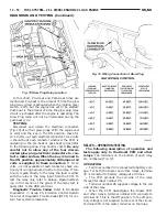
GLOW PLUG RELAY TEST
The glow plug relay is located in the engine com-
partment on the left–inner fender (Fig. 15).
When the ignition (key) switch is placed in the ON
position, a signal is sent to the PCM relating current
engine coolant temperature. This signal is sent from
the engine coolant temperature sensor.
After receiving this signal, the PCM will deter-
mine if, when and for how long a period the glow
plug relay should be activated. This is done before,
during and after the engine is started. Whenever the
glow plug relay is activated, it will control the 12V+
100 amp circuit for the operation of the four glow
plugs.
The Glow Plug lamp is tied to this circuit. Lamp
operation is also controlled by the PCM.
With a cold engine, the glow plug relay and glow
plugs may be activated for a maximum time of 200
seconds. Refer to the Glow Plug Control chart for a
temperature/time comparison of glow plug relay oper-
ation.
Fig. 14 Typical Glow Plug Tester
NS/GS
FUEL SYSTEM—2.5L DIESEL ENGINE/2.0L GAS ENGINE
14 - 51
DIAGNOSIS AND TESTING (Continued)
Summary of Contents for 1998 Voyager
Page 8: ...FASTENER IDENTIFICATION NS INTRODUCTION 5 GENERAL INFORMATION Continued ...
Page 9: ...FASTENER STRENGTH 6 INTRODUCTION NS GENERAL INFORMATION Continued ...
Page 11: ...METRIC CONVERSION 8 INTRODUCTION NS GENERAL INFORMATION Continued ...
Page 12: ...TORQUE SPECIFICATIONS NS INTRODUCTION 9 GENERAL INFORMATION Continued ...
Page 16: ......
Page 26: ......
Page 93: ...RED BRAKE WARNING LAMP FUNCTION NS BRAKES 5 11 DIAGNOSIS AND TESTING Continued ...
Page 94: ...POWER BRAKE SYSTEM DIAGNOSTICS 5 12 BRAKES NS DIAGNOSIS AND TESTING Continued ...
Page 95: ...VEHICLE ROAD TEST BRAKE NOISE NS BRAKES 5 13 DIAGNOSIS AND TESTING Continued ...
Page 222: ...COOLING SYSTEM DIAGNOSIS 7 8 COOLING SYSTEM NS DIAGNOSIS AND TESTING Continued ...
Page 223: ...NS COOLING SYSTEM 7 9 DIAGNOSIS AND TESTING Continued ...
Page 224: ...7 10 COOLING SYSTEM NS DIAGNOSIS AND TESTING Continued ...
Page 225: ...NS COOLING SYSTEM 7 11 DIAGNOSIS AND TESTING Continued ...
Page 226: ...7 12 COOLING SYSTEM NS DIAGNOSIS AND TESTING Continued ...
Page 280: ......
Page 286: ......
Page 289: ...CHARGING SYSTEM SCHEMATIC TYPICAL NS CHARGING SYSTEM 8C 3 DIAGNOSIS AND TESTING Continued ...
Page 291: ...CHARGING SYSTEM TEST NS CHARGING SYSTEM 8C 5 DIAGNOSIS AND TESTING Continued ...
Page 292: ...OVERCHARGE TEST 8C 6 CHARGING SYSTEM NS DIAGNOSIS AND TESTING Continued ...
Page 294: ...VOLTAGE DROP TEST 8C 8 CHARGING SYSTEM NS ...
Page 298: ......
Page 372: ......
Page 377: ...NS GS INSTRUMENT PANEL AND SYSTEMS 8E 5 DIAGNOSIS AND TESTING Continued ...
Page 378: ...8E 6 INSTRUMENT PANEL AND SYSTEMS NS GS DIAGNOSIS AND TESTING Continued ...
Page 379: ...NS GS INSTRUMENT PANEL AND SYSTEMS 8E 7 DIAGNOSIS AND TESTING Continued ...
Page 380: ...8E 8 INSTRUMENT PANEL AND SYSTEMS NS GS DIAGNOSIS AND TESTING Continued ...
Page 381: ...NS GS INSTRUMENT PANEL AND SYSTEMS 8E 9 DIAGNOSIS AND TESTING Continued ...
Page 382: ...8E 10 INSTRUMENT PANEL AND SYSTEMS NS GS DIAGNOSIS AND TESTING Continued ...
Page 383: ...NS GS INSTRUMENT PANEL AND SYSTEMS 8E 11 DIAGNOSIS AND TESTING Continued ...
Page 384: ...8E 12 INSTRUMENT PANEL AND SYSTEMS NS GS DIAGNOSIS AND TESTING Continued ...
Page 385: ...NS GS INSTRUMENT PANEL AND SYSTEMS 8E 13 DIAGNOSIS AND TESTING Continued ...
Page 386: ...8E 14 INSTRUMENT PANEL AND SYSTEMS NS GS DIAGNOSIS AND TESTING Continued ...
Page 402: ......
Page 428: ......
Page 440: ......
Page 478: ......
Page 496: ......
Page 504: ......
Page 508: ......
Page 524: ......
Page 542: ......
Page 546: ......
Page 550: ......
Page 559: ...SPECIAL TOOLS SPECIAL TOOL Degausser 6029 NS OVERHEAD CONSOLE 8V 9 ...
Page 560: ......
Page 562: ......
Page 564: ...8W 01 2 8W 01 GENERAL INFORMATION NS GS DESCRIPTION AND OPERATION Continued ...
Page 565: ...NS GS 8W 01 GENERAL INFORMATION 8W 01 3 DESCRIPTION AND OPERATION Continued ...
Page 580: ......
Page 616: ......
Page 660: ......
Page 664: ......
Page 704: ......
Page 718: ......
Page 728: ......
Page 740: ......
Page 744: ......
Page 758: ......
Page 768: ......
Page 784: ......
Page 792: ......
Page 796: ......
Page 800: ......
Page 814: ......
Page 822: ......
Page 826: ......
Page 832: ......
Page 836: ......
Page 840: ......
Page 876: ......
Page 1024: ......
Page 1220: ...Fig 3 Lubrication Lines 9 42 ENGINE NS GS DESCRIPTION AND OPERATION Continued ...
Page 1224: ...ENGINE DIAGNOSIS MECHANICAL CONT 9 46 ENGINE NS GS DIAGNOSIS AND TESTING Continued ...
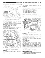
Page 1286: ...Fig 5 Front Crossmember Dimensions 13 6 FRAME AND BUMPERS NS SPECIFICATIONS Continued ...
Page 1287: ...Fig 6 Engine Compartment Top View NS FRAME AND BUMPERS 13 7 SPECIFICATIONS Continued ...
Page 1289: ...Fig 8 Full Vehicle Bottom View NS FRAME AND BUMPERS 13 9 SPECIFICATIONS Continued ...
Page 1291: ...Fig 11 Body Side Openings NS FRAME AND BUMPERS 13 11 SPECIFICATIONS Continued ...
Page 1292: ......
Page 1302: ...FUEL PRESSURE BELOW SPECIFICATIONS 14 8 FUEL SYSTEM NS DIAGNOSIS AND TESTING Continued ...
Page 1304: ...FUEL INJECTOR DIAGNOSIS 14 10 FUEL SYSTEM NS DIAGNOSIS AND TESTING Continued ...
Page 1368: ......
Page 1426: ......
Page 1472: ......
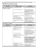
Page 1479: ...Diagnosis Guide NS TRANSAXLE AND POWER TRANSFER UNIT 21 5 DIAGNOSIS AND TESTING Continued ...
Page 1480: ...Diagnosis Guide 21 6 TRANSAXLE AND POWER TRANSFER UNIT NS DIAGNOSIS AND TESTING Continued ...
Page 1481: ...Diagnosis Guide NS TRANSAXLE AND POWER TRANSFER UNIT 21 7 DIAGNOSIS AND TESTING Continued ...
Page 1482: ...Diagnosis Guide 21 8 TRANSAXLE AND POWER TRANSFER UNIT NS DIAGNOSIS AND TESTING Continued ...
Page 1483: ...Diagnosis Guide NS TRANSAXLE AND POWER TRANSFER UNIT 21 9 DIAGNOSIS AND TESTING Continued ...
Page 1484: ...Diagnosis Guide 21 10 TRANSAXLE AND POWER TRANSFER UNIT NS DIAGNOSIS AND TESTING Continued ...
Page 1485: ...Diagnosis Guide NS TRANSAXLE AND POWER TRANSFER UNIT 21 11 DIAGNOSIS AND TESTING Continued ...
Page 1486: ...Diagnosis Guide 21 12 TRANSAXLE AND POWER TRANSFER UNIT NS DIAGNOSIS AND TESTING Continued ...
Page 1656: ......
Page 1723: ...LEAD CORRECTION CHART NS TIRES AND WHEELS 22 5 DIAGNOSIS AND TESTING Continued ...
Page 1726: ...SPECIFICATIONS TIRE SPECIFICATIONS 22 8 TIRES AND WHEELS NS ...
Page 1866: ......
Page 1904: ......
Page 1928: ......