


GENERAL INFORMATION
31TH TRANSAXLE
NOTE: Safety goggles should be worn at all times
when working on these transaxles.
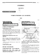
This transaxle combines torque converter, three
speed transmission, final drive gearing, and differen-
tial into a front wheel drive system. The identifica-
tion markings and usage of the transaxle are charted
in Diagnosis and Tests.
NOTE: Transaxle operation requirements are differ-
ent for each vehicle and engine combination. Some
internal parts will be different to provide for this.
Therefore, when replacing parts, refer to the seven
digit part number stamped on rear of the transaxle
oil pan flange.
Within this transaxle, there are three primary
areas:
(1) Main center line plus valve body.
(2) Transfer shaft center line (includes governor
and parking sprag).
(3) Differential center line.
(4) Center distances between the main rotating
parts in these three areas are held precise to main-
tain a low noise level.
(5) The torque converter, transaxle area, and dif-
ferential are housed in an integral aluminum die
casting. The differential oil sump is common
with the transaxle sump. Separate filling of the
differential is NOT necessary.
(6) The torque converter is attached to the crank-
shaft through a flexible driving plate. Cooling of the
converter is accomplished by circulating the tran-
saxle fluid through a remote cooler. There are two
types of coolers used. An oil-to-water type cooler
located in the radiator side tank and/or an oil-to air
heat exchanger. The torque converter assembly is a
sealed unit that cannot be disassembled.
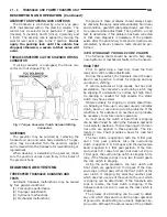
(7) The transaxle fluid is filtered by an internal fil-
ter attached to the lower side of the valve body
assembly.
(8) Engine torque is transmitted to the torque con-
verter then, through the input shaft to multiple-disc
clutches in the transaxle. The power flow depends on
the application of the clutches and bands. Refer to
Elements in Use Chart in Diagnosis and Tests sec-
tion.
(9) The transaxle consists of:
•
Two multiple-disc clutches
•
An overrunning clutch
•
Two servos
•
A hydraulic accumulator
•
Two bands
•
Two planetary gear sets
This provides three forward ratios and a reverse
ratio. The common sun gear of the planetary gear
sets is connected to the front clutch by a driving
shell. The drive shell is splined to the sun gear and
front clutch retainer. The hydraulic system consists
of an oil pump, and a single valve body which con-
tains all of the valves except the governor valves.
The transaxle sump and differential sump are both
vented through the dipstick. Output torque from the
main center line is delivered through helical gears to
the transfer shaft. This gear set is a factor of the
final drive (axle) ratio. The shaft also carries the gov-
ernor and parking sprag. An integral helical gear on
the transfer shaft drives the differential ring gear.
The final drive gearing is completed with one of two
gear ratios of 2.98 or 3.19 depending on model and
application.
FLUID LEVEL AND CONDITION
NOTE: The transmission and differential sump have
a common oil sump with a communicating opening
between the two.
The torque converter fills in both the P Park and N
Neutral positions. Place the selector lever in P Park
to be sure that the fluid level check is accurate. The
engine should be running at idle speed for at
least one minute, with the vehicle on level
ground. This will assure complete oil level sta-
bilization between differential and transmis-
sion. The fluid should be at normal operating
temperature (approximately 82 C. or 180 F.). The
fluid level is correct if it is in the HOT region (cross-
hatched area) on the dipstick.
Low fluid level can cause a variety of conditions
because it allows the pump to take in air along with
the fluid. As in any hydraulic system, air bubbles
make the fluid spongy, therefore, pressures will be
low and build up slowly.
Improper filling can also raise the fluid level too
high. When the transaxle has too much fluid, the
gears churn up foam and cause the same conditions
which occur with a low fluid level.
In either case, the air bubbles can cause overheat-
ing, fluid oxidation, and varnishing. This can inter-
fere with normal valve, clutch, and servo operation.
Foaming can also result in fluid escaping from the
transaxle dipstick where it may be mistaken for a
leak.
Along with fluid level, it is important to check the
condition of the fluid. When the fluid smells burned,
and is contaminated with metal or friction material
particles, a complete transaxle overhaul is needed.
Be sure to examine the fluid on the dipstick closely.
21 - 2
TRANSAXLE AND POWER TRANSFER UNIT
NS
Summary of Contents for 1998 Voyager
Page 8: ...FASTENER IDENTIFICATION NS INTRODUCTION 5 GENERAL INFORMATION Continued ...
Page 9: ...FASTENER STRENGTH 6 INTRODUCTION NS GENERAL INFORMATION Continued ...
Page 11: ...METRIC CONVERSION 8 INTRODUCTION NS GENERAL INFORMATION Continued ...
Page 12: ...TORQUE SPECIFICATIONS NS INTRODUCTION 9 GENERAL INFORMATION Continued ...
Page 16: ......
Page 26: ......
Page 93: ...RED BRAKE WARNING LAMP FUNCTION NS BRAKES 5 11 DIAGNOSIS AND TESTING Continued ...
Page 94: ...POWER BRAKE SYSTEM DIAGNOSTICS 5 12 BRAKES NS DIAGNOSIS AND TESTING Continued ...
Page 95: ...VEHICLE ROAD TEST BRAKE NOISE NS BRAKES 5 13 DIAGNOSIS AND TESTING Continued ...
Page 222: ...COOLING SYSTEM DIAGNOSIS 7 8 COOLING SYSTEM NS DIAGNOSIS AND TESTING Continued ...
Page 223: ...NS COOLING SYSTEM 7 9 DIAGNOSIS AND TESTING Continued ...
Page 224: ...7 10 COOLING SYSTEM NS DIAGNOSIS AND TESTING Continued ...
Page 225: ...NS COOLING SYSTEM 7 11 DIAGNOSIS AND TESTING Continued ...
Page 226: ...7 12 COOLING SYSTEM NS DIAGNOSIS AND TESTING Continued ...
Page 280: ......
Page 286: ......
Page 289: ...CHARGING SYSTEM SCHEMATIC TYPICAL NS CHARGING SYSTEM 8C 3 DIAGNOSIS AND TESTING Continued ...
Page 291: ...CHARGING SYSTEM TEST NS CHARGING SYSTEM 8C 5 DIAGNOSIS AND TESTING Continued ...
Page 292: ...OVERCHARGE TEST 8C 6 CHARGING SYSTEM NS DIAGNOSIS AND TESTING Continued ...
Page 294: ...VOLTAGE DROP TEST 8C 8 CHARGING SYSTEM NS ...
Page 298: ......
Page 372: ......
Page 377: ...NS GS INSTRUMENT PANEL AND SYSTEMS 8E 5 DIAGNOSIS AND TESTING Continued ...
Page 378: ...8E 6 INSTRUMENT PANEL AND SYSTEMS NS GS DIAGNOSIS AND TESTING Continued ...
Page 379: ...NS GS INSTRUMENT PANEL AND SYSTEMS 8E 7 DIAGNOSIS AND TESTING Continued ...
Page 380: ...8E 8 INSTRUMENT PANEL AND SYSTEMS NS GS DIAGNOSIS AND TESTING Continued ...
Page 381: ...NS GS INSTRUMENT PANEL AND SYSTEMS 8E 9 DIAGNOSIS AND TESTING Continued ...
Page 382: ...8E 10 INSTRUMENT PANEL AND SYSTEMS NS GS DIAGNOSIS AND TESTING Continued ...
Page 383: ...NS GS INSTRUMENT PANEL AND SYSTEMS 8E 11 DIAGNOSIS AND TESTING Continued ...
Page 384: ...8E 12 INSTRUMENT PANEL AND SYSTEMS NS GS DIAGNOSIS AND TESTING Continued ...
Page 385: ...NS GS INSTRUMENT PANEL AND SYSTEMS 8E 13 DIAGNOSIS AND TESTING Continued ...
Page 386: ...8E 14 INSTRUMENT PANEL AND SYSTEMS NS GS DIAGNOSIS AND TESTING Continued ...
Page 402: ......
Page 428: ......
Page 440: ......
Page 478: ......
Page 496: ......
Page 504: ......
Page 508: ......
Page 524: ......
Page 542: ......
Page 546: ......
Page 550: ......
Page 559: ...SPECIAL TOOLS SPECIAL TOOL Degausser 6029 NS OVERHEAD CONSOLE 8V 9 ...
Page 560: ......
Page 562: ......
Page 564: ...8W 01 2 8W 01 GENERAL INFORMATION NS GS DESCRIPTION AND OPERATION Continued ...
Page 565: ...NS GS 8W 01 GENERAL INFORMATION 8W 01 3 DESCRIPTION AND OPERATION Continued ...
Page 580: ......
Page 616: ......
Page 660: ......
Page 664: ......
Page 704: ......
Page 718: ......
Page 728: ......
Page 740: ......
Page 744: ......
Page 758: ......
Page 768: ......
Page 784: ......
Page 792: ......
Page 796: ......
Page 800: ......
Page 814: ......
Page 822: ......
Page 826: ......
Page 832: ......
Page 836: ......
Page 840: ......
Page 876: ......
Page 1024: ......
Page 1220: ...Fig 3 Lubrication Lines 9 42 ENGINE NS GS DESCRIPTION AND OPERATION Continued ...
Page 1224: ...ENGINE DIAGNOSIS MECHANICAL CONT 9 46 ENGINE NS GS DIAGNOSIS AND TESTING Continued ...
Page 1286: ...Fig 5 Front Crossmember Dimensions 13 6 FRAME AND BUMPERS NS SPECIFICATIONS Continued ...
Page 1287: ...Fig 6 Engine Compartment Top View NS FRAME AND BUMPERS 13 7 SPECIFICATIONS Continued ...
Page 1289: ...Fig 8 Full Vehicle Bottom View NS FRAME AND BUMPERS 13 9 SPECIFICATIONS Continued ...
Page 1291: ...Fig 11 Body Side Openings NS FRAME AND BUMPERS 13 11 SPECIFICATIONS Continued ...
Page 1292: ......
Page 1302: ...FUEL PRESSURE BELOW SPECIFICATIONS 14 8 FUEL SYSTEM NS DIAGNOSIS AND TESTING Continued ...
Page 1304: ...FUEL INJECTOR DIAGNOSIS 14 10 FUEL SYSTEM NS DIAGNOSIS AND TESTING Continued ...
Page 1368: ......
Page 1426: ......
Page 1472: ......
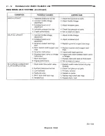
Page 1479: ...Diagnosis Guide NS TRANSAXLE AND POWER TRANSFER UNIT 21 5 DIAGNOSIS AND TESTING Continued ...
Page 1480: ...Diagnosis Guide 21 6 TRANSAXLE AND POWER TRANSFER UNIT NS DIAGNOSIS AND TESTING Continued ...
Page 1481: ...Diagnosis Guide NS TRANSAXLE AND POWER TRANSFER UNIT 21 7 DIAGNOSIS AND TESTING Continued ...
Page 1482: ...Diagnosis Guide 21 8 TRANSAXLE AND POWER TRANSFER UNIT NS DIAGNOSIS AND TESTING Continued ...
Page 1483: ...Diagnosis Guide NS TRANSAXLE AND POWER TRANSFER UNIT 21 9 DIAGNOSIS AND TESTING Continued ...
Page 1484: ...Diagnosis Guide 21 10 TRANSAXLE AND POWER TRANSFER UNIT NS DIAGNOSIS AND TESTING Continued ...
Page 1485: ...Diagnosis Guide NS TRANSAXLE AND POWER TRANSFER UNIT 21 11 DIAGNOSIS AND TESTING Continued ...
Page 1486: ...Diagnosis Guide 21 12 TRANSAXLE AND POWER TRANSFER UNIT NS DIAGNOSIS AND TESTING Continued ...
Page 1656: ......
Page 1723: ...LEAD CORRECTION CHART NS TIRES AND WHEELS 22 5 DIAGNOSIS AND TESTING Continued ...
Page 1726: ...SPECIFICATIONS TIRE SPECIFICATIONS 22 8 TIRES AND WHEELS NS ...
Page 1866: ......
Page 1904: ......
Page 1928: ......