


front seal is retained in the oil pump case and the
rear is retained in a block-mounted housing.
PISTONS: Are aluminum alloy with a steel strut,
short height, and thin wall so as to be autothermic
and light weight. The piston head with valve
recesses, in combination with the cylinder head,
forms a compact spherical head with clearance for
total valve lift with pistons at top dead center. The
piston skirt, top and second ring lands are finished to
a tapered roughness for oil retention and high resis-
tance to scuffing. Piston pins, pressed into place, join
the pistons to the connecting rods.
CYLINDER HEAD: The alloy cylinder heads fea-
ture cross-flow type intake and exhaust ports. Valve
guides and inserts are hardened cast iron. Valves of
heat resistance steel are arranged in a V with each
camshaft on center. To improve combustion speed the
chambers are a compact spherical design with a
squish area of approximately 30 percent of the piston
top area. The cylinder heads are common to either
cylinder bank by reversing the direction of installa-
tion.
CAMSHAFTS: Two overhead camshafts provide
valve actuation, one front (radiator side of cylinder
bank) and one rear. The front camshaft is provided
with a distributor drive and is longer. Both cam-
shafts are supported by four bearing journals, thrust
for the front camshaft is taken at journal two and
the rear at journal three. Front and rear camshaft
driving sprockets are interchangeable. The sprockets
and the engine water pump are driven by a single
notched timing belt.
ROCKER ARM SHAFTS: The shafts are retained
by the camshaft bearing journal caps. Four shafts are
used, one for each intake and exhaust rocker arm
assembly on each cylinder head. The hollow shafts
provide a duct for lubricating oil flow from the cylin-
der head to the valve mechanisms.
ROCKER ARMS: Are of light weight die-cast with
roller type follower operating against the cam shaft.
The valve actuating end of the rocker arms are
machined to retain hydraulic lash adjusters, elimi-
nating valve lash adjustment.
VALVES: Are made of heat resistant steel, valve
springs are especially designed to be short. The valve
spring wire cross-section is oval shaped and provides
the same spring tension as longer springs. Valve
spring retainers, locks and seals are conventional.
INTAKE MANIFOLD: The aluminum alloy mani-
fold is a cross type with long runners to improve
inertia. The runners, attaching below at the cylinder
head, also attach above and support an air plenum.
The air plenum chamber absorbs air pulsations cre-
ated during the suction phase of each cylinder.
EXHAUST MANIFOLDS: Both manifolds are a
log style made of ductile cast iron. Exhaust gasses,
collected from the front cylinder bank, leave the front
manifold through an end outlet and are fed through
an upper crossover tube to the rear manifold. The
collected exhaust from both manifolds are combined,
and exit to the exhaust pipe through an articulated
joint.
DIAGNOSIS AND TESTING
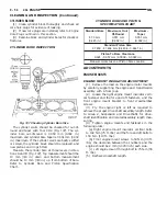
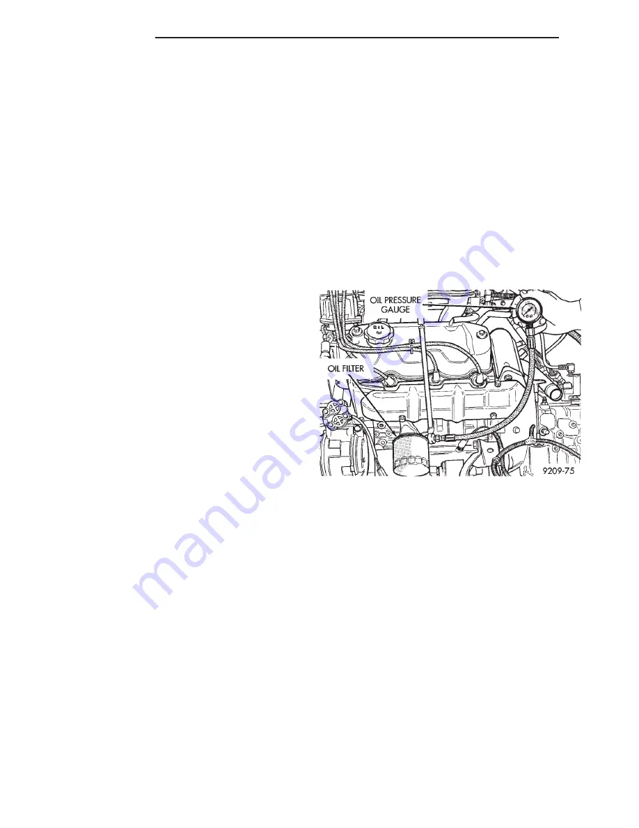
CHECKING ENGINE OIL PRESSURE
Check oil pressure using gauge at oil pressure
switch location. Oil pressure should be 41 kPa ( 6
psi.) at idle or 241 to 517 kPa (35 to 75 psi.) at 3000
RPM.
(1) Remove pressure sending unit and install oil
pressure gauge. (Fig. 2).
CAUTION:
If oil pressure is 0 at idle, Do Not Run
engine at 3000 RPM.
(2) Warm engine at high idle until thermostat
opens.
SERVICE PROCEDURES
AUTO LASH ADJUSTER
The automatic lash adjusters are precision units
installed in machined openings in the valve actuating
ends of the rocker arms. Do not disassemble the auto
lash adjuster.
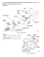
FUNCTION CHECK
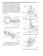
Check auto adjusters for free play by inserting a
small wire through the air bleed hole in the rocker
arm and very lightly pushing the auto adjuster ball
check down (Fig. 3). While lightly holding the check
ball down move the rocker up and down to check for
free play. If there is no play replace the adjuster.
Fig. 2 Checking Engine Oil Pressure
9 - 62
3.0L ENGINE
NS
DESCRIPTION AND OPERATION (Continued)
Summary of Contents for 1998 Voyager
Page 8: ...FASTENER IDENTIFICATION NS INTRODUCTION 5 GENERAL INFORMATION Continued ...
Page 9: ...FASTENER STRENGTH 6 INTRODUCTION NS GENERAL INFORMATION Continued ...
Page 11: ...METRIC CONVERSION 8 INTRODUCTION NS GENERAL INFORMATION Continued ...
Page 12: ...TORQUE SPECIFICATIONS NS INTRODUCTION 9 GENERAL INFORMATION Continued ...
Page 16: ......
Page 26: ......
Page 93: ...RED BRAKE WARNING LAMP FUNCTION NS BRAKES 5 11 DIAGNOSIS AND TESTING Continued ...
Page 94: ...POWER BRAKE SYSTEM DIAGNOSTICS 5 12 BRAKES NS DIAGNOSIS AND TESTING Continued ...
Page 95: ...VEHICLE ROAD TEST BRAKE NOISE NS BRAKES 5 13 DIAGNOSIS AND TESTING Continued ...
Page 222: ...COOLING SYSTEM DIAGNOSIS 7 8 COOLING SYSTEM NS DIAGNOSIS AND TESTING Continued ...
Page 223: ...NS COOLING SYSTEM 7 9 DIAGNOSIS AND TESTING Continued ...
Page 224: ...7 10 COOLING SYSTEM NS DIAGNOSIS AND TESTING Continued ...
Page 225: ...NS COOLING SYSTEM 7 11 DIAGNOSIS AND TESTING Continued ...
Page 226: ...7 12 COOLING SYSTEM NS DIAGNOSIS AND TESTING Continued ...
Page 280: ......
Page 286: ......
Page 289: ...CHARGING SYSTEM SCHEMATIC TYPICAL NS CHARGING SYSTEM 8C 3 DIAGNOSIS AND TESTING Continued ...
Page 291: ...CHARGING SYSTEM TEST NS CHARGING SYSTEM 8C 5 DIAGNOSIS AND TESTING Continued ...
Page 292: ...OVERCHARGE TEST 8C 6 CHARGING SYSTEM NS DIAGNOSIS AND TESTING Continued ...
Page 294: ...VOLTAGE DROP TEST 8C 8 CHARGING SYSTEM NS ...
Page 298: ......
Page 372: ......
Page 377: ...NS GS INSTRUMENT PANEL AND SYSTEMS 8E 5 DIAGNOSIS AND TESTING Continued ...
Page 378: ...8E 6 INSTRUMENT PANEL AND SYSTEMS NS GS DIAGNOSIS AND TESTING Continued ...
Page 379: ...NS GS INSTRUMENT PANEL AND SYSTEMS 8E 7 DIAGNOSIS AND TESTING Continued ...
Page 380: ...8E 8 INSTRUMENT PANEL AND SYSTEMS NS GS DIAGNOSIS AND TESTING Continued ...
Page 381: ...NS GS INSTRUMENT PANEL AND SYSTEMS 8E 9 DIAGNOSIS AND TESTING Continued ...
Page 382: ...8E 10 INSTRUMENT PANEL AND SYSTEMS NS GS DIAGNOSIS AND TESTING Continued ...
Page 383: ...NS GS INSTRUMENT PANEL AND SYSTEMS 8E 11 DIAGNOSIS AND TESTING Continued ...
Page 384: ...8E 12 INSTRUMENT PANEL AND SYSTEMS NS GS DIAGNOSIS AND TESTING Continued ...
Page 385: ...NS GS INSTRUMENT PANEL AND SYSTEMS 8E 13 DIAGNOSIS AND TESTING Continued ...
Page 386: ...8E 14 INSTRUMENT PANEL AND SYSTEMS NS GS DIAGNOSIS AND TESTING Continued ...
Page 402: ......
Page 428: ......
Page 440: ......
Page 478: ......
Page 496: ......
Page 504: ......
Page 508: ......
Page 524: ......
Page 542: ......
Page 546: ......
Page 550: ......
Page 559: ...SPECIAL TOOLS SPECIAL TOOL Degausser 6029 NS OVERHEAD CONSOLE 8V 9 ...
Page 560: ......
Page 562: ......
Page 564: ...8W 01 2 8W 01 GENERAL INFORMATION NS GS DESCRIPTION AND OPERATION Continued ...
Page 565: ...NS GS 8W 01 GENERAL INFORMATION 8W 01 3 DESCRIPTION AND OPERATION Continued ...
Page 580: ......
Page 616: ......
Page 660: ......
Page 664: ......
Page 704: ......
Page 718: ......
Page 728: ......
Page 740: ......
Page 744: ......
Page 758: ......
Page 768: ......
Page 784: ......
Page 792: ......
Page 796: ......
Page 800: ......
Page 814: ......
Page 822: ......
Page 826: ......
Page 832: ......
Page 836: ......
Page 840: ......
Page 876: ......
Page 1024: ......
Page 1220: ...Fig 3 Lubrication Lines 9 42 ENGINE NS GS DESCRIPTION AND OPERATION Continued ...
Page 1224: ...ENGINE DIAGNOSIS MECHANICAL CONT 9 46 ENGINE NS GS DIAGNOSIS AND TESTING Continued ...
Page 1286: ...Fig 5 Front Crossmember Dimensions 13 6 FRAME AND BUMPERS NS SPECIFICATIONS Continued ...
Page 1287: ...Fig 6 Engine Compartment Top View NS FRAME AND BUMPERS 13 7 SPECIFICATIONS Continued ...
Page 1289: ...Fig 8 Full Vehicle Bottom View NS FRAME AND BUMPERS 13 9 SPECIFICATIONS Continued ...
Page 1291: ...Fig 11 Body Side Openings NS FRAME AND BUMPERS 13 11 SPECIFICATIONS Continued ...
Page 1292: ......
Page 1302: ...FUEL PRESSURE BELOW SPECIFICATIONS 14 8 FUEL SYSTEM NS DIAGNOSIS AND TESTING Continued ...
Page 1304: ...FUEL INJECTOR DIAGNOSIS 14 10 FUEL SYSTEM NS DIAGNOSIS AND TESTING Continued ...
Page 1368: ......
Page 1426: ......
Page 1472: ......
Page 1479: ...Diagnosis Guide NS TRANSAXLE AND POWER TRANSFER UNIT 21 5 DIAGNOSIS AND TESTING Continued ...
Page 1480: ...Diagnosis Guide 21 6 TRANSAXLE AND POWER TRANSFER UNIT NS DIAGNOSIS AND TESTING Continued ...
Page 1481: ...Diagnosis Guide NS TRANSAXLE AND POWER TRANSFER UNIT 21 7 DIAGNOSIS AND TESTING Continued ...
Page 1482: ...Diagnosis Guide 21 8 TRANSAXLE AND POWER TRANSFER UNIT NS DIAGNOSIS AND TESTING Continued ...
Page 1483: ...Diagnosis Guide NS TRANSAXLE AND POWER TRANSFER UNIT 21 9 DIAGNOSIS AND TESTING Continued ...
Page 1484: ...Diagnosis Guide 21 10 TRANSAXLE AND POWER TRANSFER UNIT NS DIAGNOSIS AND TESTING Continued ...
Page 1485: ...Diagnosis Guide NS TRANSAXLE AND POWER TRANSFER UNIT 21 11 DIAGNOSIS AND TESTING Continued ...
Page 1486: ...Diagnosis Guide 21 12 TRANSAXLE AND POWER TRANSFER UNIT NS DIAGNOSIS AND TESTING Continued ...
Page 1656: ......
Page 1723: ...LEAD CORRECTION CHART NS TIRES AND WHEELS 22 5 DIAGNOSIS AND TESTING Continued ...
Page 1726: ...SPECIFICATIONS TIRE SPECIFICATIONS 22 8 TIRES AND WHEELS NS ...
Page 1866: ......
Page 1904: ......
Page 1928: ......