


CAUTION: Never coat the inside of spark plug
boots with silicone grease. Some types of silicone
grease can damage the ignition cable conductor.
SPARK PLUG CABLES #3 AND #5
REMOVAL
(1) Remove the resonator.
(2) Grasp the spark plug boot/heat shield as close
as possible to the spark plug. Twist the boot
slightly to break its seal with the plug and pull
straight back. Do not use pliers, pull on the
ignition cable, or pull the spark plug boot at an
angle. This could damage the spark plug insulator,
terminal, or the cable insulation. Wipe spark plug
insulator clean with a dry cloth before installation.
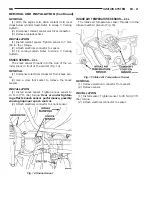
(3) Remove the cable from the retaining bracket.
Make sure that they are also detached from the rear
retaining clip mounted on the rear of the intake
manifold.
INSTALLATION
(1) When installing the spark plug cables, make
sure the coil and spark plug insulator and terminals
are fully seated. A click sound should be heard or
terminal engagement is felt when the terminals
are properly attached.
(2) Install the cable into the retaining bracket.
Make sure that they are also attached to the rear
retaining clip mounted on the rear of the intake
manifold.
(3) Install the resonator.
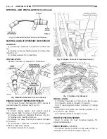
SPARK PLUG CABLE #1
REMOVAL
(1) Remove the accessory drive belt, refer to Group
7, Cooling.
(2) Remove the four bolts from the upper half of
the generator bracket.
(3) Push the Generator rearward.
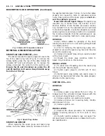
(4) Grasp the spark plug boot/shield assembly as
close as possible to the spark plug. Twist the boot
slightly to break its seal with the plug and pull
straight back. Do not use pliers, pull on the
ignition cable, or pull the spark plug boot at an
angle. This could damage the spark plug insulator,
terminal, or the cable insulation. Wipe spark plug
insulator clean with a dry cloth before installation.
(5) Remove the cable from the retaining bracket.
INSTALLATION
(1) When installing the spark plug cables, make
sure the coil and spark plug insulator and terminals
are fully seated. A click sound should be heard or
terminal engagement is felt when the terminals
are properly attached.
(2) Rotate Generator back into place.
(3) Install upper Generator bracket with the four
bolts.
(4) Install the accessory drive belt, refer to Group
7, Cooling.
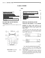
SPARK PLUG SERVICE—3.3/3.8L ENGINES
WARNING: The
ignition
cables
should
not
be
removed while the engine is hot. This could cause
server injury/burns and can cause damage to the
ignition cables.
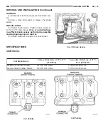
Use extreme care when removing and installing
the spark plug cables.
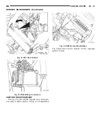
The spark plug boot heat shield needs to be
installed correctly on the boot before being installed
on the engine (Fig. 1). If it is not installed correctly
engine misfire would occur.
Do not use pliers to pull the boot/heat shield
assembly from the spark plugs. This will damage the
shield assembly.
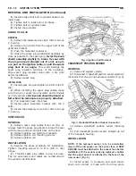
SPARK PLUG #3 AND #5
REMOVAL
(1) Remove the resonator.
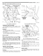
(2) Remove intake strut to cylinder head bolt at
cylinder head.
(3) Loosen bolt for intake strut at intake.
(4) Swing strut away.
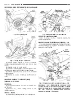
(5) Grasp the spark plug boot/shield assembly as
close as possible to the spark plug. Twist the boot/
shield assembly slightly to break the seal with
the plug and pull straight out. Do not use pli-
ers, pull on the ignition cable, or pull the spark
plug boot at an angle. This could damage the
spark plug insulator, terminal, heat shield or the
insulation. Wipe spark plug insulator clean with a
dry cloth before installation.
(6) Remove spark plug
INSTALLATION
(1) Install spark plug and tighten to 28 N·m (20 ft.
lbs.).
(2) When installing the spark plug cables, make
sure spark plug insulator and terminals are fully
seated. A click sound should be heard or felt
when the terminals are properly attached.
(3) Install the cable into the retaining bracket.
Make sure that they are also attached to the rear
retaining clip mounted on the rear of the intake
manifold.
(4) Swing strut back into place.
NS
IGNITION SYSTEM
8D - 29
REMOVAL AND INSTALLATION (Continued)
Summary of Contents for 1998 Voyager
Page 8: ...FASTENER IDENTIFICATION NS INTRODUCTION 5 GENERAL INFORMATION Continued ...
Page 9: ...FASTENER STRENGTH 6 INTRODUCTION NS GENERAL INFORMATION Continued ...
Page 11: ...METRIC CONVERSION 8 INTRODUCTION NS GENERAL INFORMATION Continued ...
Page 12: ...TORQUE SPECIFICATIONS NS INTRODUCTION 9 GENERAL INFORMATION Continued ...
Page 16: ......
Page 26: ......
Page 93: ...RED BRAKE WARNING LAMP FUNCTION NS BRAKES 5 11 DIAGNOSIS AND TESTING Continued ...
Page 94: ...POWER BRAKE SYSTEM DIAGNOSTICS 5 12 BRAKES NS DIAGNOSIS AND TESTING Continued ...
Page 95: ...VEHICLE ROAD TEST BRAKE NOISE NS BRAKES 5 13 DIAGNOSIS AND TESTING Continued ...
Page 222: ...COOLING SYSTEM DIAGNOSIS 7 8 COOLING SYSTEM NS DIAGNOSIS AND TESTING Continued ...
Page 223: ...NS COOLING SYSTEM 7 9 DIAGNOSIS AND TESTING Continued ...
Page 224: ...7 10 COOLING SYSTEM NS DIAGNOSIS AND TESTING Continued ...
Page 225: ...NS COOLING SYSTEM 7 11 DIAGNOSIS AND TESTING Continued ...
Page 226: ...7 12 COOLING SYSTEM NS DIAGNOSIS AND TESTING Continued ...
Page 280: ......
Page 286: ......
Page 289: ...CHARGING SYSTEM SCHEMATIC TYPICAL NS CHARGING SYSTEM 8C 3 DIAGNOSIS AND TESTING Continued ...
Page 291: ...CHARGING SYSTEM TEST NS CHARGING SYSTEM 8C 5 DIAGNOSIS AND TESTING Continued ...
Page 292: ...OVERCHARGE TEST 8C 6 CHARGING SYSTEM NS DIAGNOSIS AND TESTING Continued ...
Page 294: ...VOLTAGE DROP TEST 8C 8 CHARGING SYSTEM NS ...
Page 298: ......
Page 372: ......
Page 377: ...NS GS INSTRUMENT PANEL AND SYSTEMS 8E 5 DIAGNOSIS AND TESTING Continued ...
Page 378: ...8E 6 INSTRUMENT PANEL AND SYSTEMS NS GS DIAGNOSIS AND TESTING Continued ...
Page 379: ...NS GS INSTRUMENT PANEL AND SYSTEMS 8E 7 DIAGNOSIS AND TESTING Continued ...
Page 380: ...8E 8 INSTRUMENT PANEL AND SYSTEMS NS GS DIAGNOSIS AND TESTING Continued ...
Page 381: ...NS GS INSTRUMENT PANEL AND SYSTEMS 8E 9 DIAGNOSIS AND TESTING Continued ...
Page 382: ...8E 10 INSTRUMENT PANEL AND SYSTEMS NS GS DIAGNOSIS AND TESTING Continued ...
Page 383: ...NS GS INSTRUMENT PANEL AND SYSTEMS 8E 11 DIAGNOSIS AND TESTING Continued ...
Page 384: ...8E 12 INSTRUMENT PANEL AND SYSTEMS NS GS DIAGNOSIS AND TESTING Continued ...
Page 385: ...NS GS INSTRUMENT PANEL AND SYSTEMS 8E 13 DIAGNOSIS AND TESTING Continued ...
Page 386: ...8E 14 INSTRUMENT PANEL AND SYSTEMS NS GS DIAGNOSIS AND TESTING Continued ...
Page 402: ......
Page 428: ......
Page 440: ......
Page 478: ......
Page 496: ......
Page 504: ......
Page 508: ......
Page 524: ......
Page 542: ......
Page 546: ......
Page 550: ......
Page 559: ...SPECIAL TOOLS SPECIAL TOOL Degausser 6029 NS OVERHEAD CONSOLE 8V 9 ...
Page 560: ......
Page 562: ......
Page 564: ...8W 01 2 8W 01 GENERAL INFORMATION NS GS DESCRIPTION AND OPERATION Continued ...
Page 565: ...NS GS 8W 01 GENERAL INFORMATION 8W 01 3 DESCRIPTION AND OPERATION Continued ...
Page 580: ......
Page 616: ......
Page 660: ......
Page 664: ......
Page 704: ......
Page 718: ......
Page 728: ......
Page 740: ......
Page 744: ......
Page 758: ......
Page 768: ......
Page 784: ......
Page 792: ......
Page 796: ......
Page 800: ......
Page 814: ......
Page 822: ......
Page 826: ......
Page 832: ......
Page 836: ......
Page 840: ......
Page 876: ......
Page 1024: ......
Page 1220: ...Fig 3 Lubrication Lines 9 42 ENGINE NS GS DESCRIPTION AND OPERATION Continued ...
Page 1224: ...ENGINE DIAGNOSIS MECHANICAL CONT 9 46 ENGINE NS GS DIAGNOSIS AND TESTING Continued ...
Page 1286: ...Fig 5 Front Crossmember Dimensions 13 6 FRAME AND BUMPERS NS SPECIFICATIONS Continued ...
Page 1287: ...Fig 6 Engine Compartment Top View NS FRAME AND BUMPERS 13 7 SPECIFICATIONS Continued ...
Page 1289: ...Fig 8 Full Vehicle Bottom View NS FRAME AND BUMPERS 13 9 SPECIFICATIONS Continued ...
Page 1291: ...Fig 11 Body Side Openings NS FRAME AND BUMPERS 13 11 SPECIFICATIONS Continued ...
Page 1292: ......
Page 1302: ...FUEL PRESSURE BELOW SPECIFICATIONS 14 8 FUEL SYSTEM NS DIAGNOSIS AND TESTING Continued ...
Page 1304: ...FUEL INJECTOR DIAGNOSIS 14 10 FUEL SYSTEM NS DIAGNOSIS AND TESTING Continued ...
Page 1368: ......
Page 1426: ......
Page 1472: ......
Page 1479: ...Diagnosis Guide NS TRANSAXLE AND POWER TRANSFER UNIT 21 5 DIAGNOSIS AND TESTING Continued ...
Page 1480: ...Diagnosis Guide 21 6 TRANSAXLE AND POWER TRANSFER UNIT NS DIAGNOSIS AND TESTING Continued ...
Page 1481: ...Diagnosis Guide NS TRANSAXLE AND POWER TRANSFER UNIT 21 7 DIAGNOSIS AND TESTING Continued ...
Page 1482: ...Diagnosis Guide 21 8 TRANSAXLE AND POWER TRANSFER UNIT NS DIAGNOSIS AND TESTING Continued ...
Page 1483: ...Diagnosis Guide NS TRANSAXLE AND POWER TRANSFER UNIT 21 9 DIAGNOSIS AND TESTING Continued ...
Page 1484: ...Diagnosis Guide 21 10 TRANSAXLE AND POWER TRANSFER UNIT NS DIAGNOSIS AND TESTING Continued ...
Page 1485: ...Diagnosis Guide NS TRANSAXLE AND POWER TRANSFER UNIT 21 11 DIAGNOSIS AND TESTING Continued ...
Page 1486: ...Diagnosis Guide 21 12 TRANSAXLE AND POWER TRANSFER UNIT NS DIAGNOSIS AND TESTING Continued ...
Page 1656: ......
Page 1723: ...LEAD CORRECTION CHART NS TIRES AND WHEELS 22 5 DIAGNOSIS AND TESTING Continued ...
Page 1726: ...SPECIFICATIONS TIRE SPECIFICATIONS 22 8 TIRES AND WHEELS NS ...
Page 1866: ......
Page 1904: ......
Page 1928: ......