


ignition coil, and oxygen sensor heating element. If
the PCM does not receive the camshaft position sen-
sor and crankshaft position sensor signals within
approximately one second, it de-energizes the ASD
relay and fuel pump relay.
The PCM energizes all injectors until it determines
crankshaft position from the camshaft position sen-
sor and crankshaft position sensor signals. The PCM
determines crankshaft position within 1 engine revo-
lution.
After determining crankshaft position, the PCM
begins energizing the injectors in sequence. The PCM
adjusts injector pulse width and controls injector syn-
chronization by turning the individual ground paths
to the injectors On and Off.
When the engine idles within
6
64 RPM of its tar-
get RPM, the PCM compares current MAP sensor
value with the atmospheric pressure value received
during the Ignition Switch On (zero RPM) mode. If
the PCM does not detect a minimum difference
between the two values, it sets a MAP diagnostic
trouble code into memory.
Once the ASD and fuel pump relays have been
energized, the PCM:
•
Determines injector pulse width based on engine
coolant temperature, MAP and the number of engine
revolutions since cranking was initiated.
•
Monitors the engine coolant temperature sensor,
camshaft position sensor, crankshaft position sensor,
MAP sensor, and throttle position sensor to deter-
mine correct ignition timing.
ENGINE WARM-UP MODE
This is a OPEN LOOP mode. The following inputs
are received by the PCM:
•
Engine coolant temperature
•
Manifold absolute pressure
•
Engine speed (crankshaft position sensor)
•
Throttle position
•
A/C switch
•
Battery voltage
The PCM adjusts injector pulse width and controls
injector synchronization by turning the individual
ground paths to the injectors On and Off.
The PCM adjusts ignition timing and engine idle
speed. Engine idle speed is adjusted through the idle
air control motor.
CRUISE OR IDLE MODE
This is a CLOSED LOOP mode. The PCM recog-
nizes an abrupt increase in throttle position or MAP
pressure as a demand for increased engine output
and vehicle acceleration. The PCM increases injector
pulse width in response to increased fuel demand.
When the engine is at operating temperature this
is a CLOSED LOOP mode. During cruising speed the
following inputs are received by the PCM:
•
Engine coolant temperature
•
Manifold absolute pressure
•
Engine speed (crankshaft position sensor)
•
Throttle position
•
Exhaust gas oxygen content
•
A/C control positions
•
Battery voltage
The PCM adjusts injector pulse width and controls
injector synchronization by turning the individual
ground paths to the injectors On and Off.
The PCM adjusts engine idle speed and ignition
timing. The PCM adjusts the air/fuel ratio according
to the oxygen content in the exhaust gas.
ACCELERATION MODE
This is a CLOSED LOOP mode. The PCM recog-
nizes an abrupt increase in throttle position or MAP
pressure as a demand for increased engine output
and vehicle acceleration. The PCM increases injector
pulse width in response to increased fuel demand.
DECELERATION MODE
This is a CLOSED LOOP mode. During decelera-
tion the following inputs are received by the PCM:
•
Engine coolant temperature
•
Manifold absolute pressure
•
Engine speed
•
Throttle position
•
Exhaust gas oxygen content
•
A/C control positions
•
Battery voltage
The PCM may receive a closed throttle input from
the Throttle Position Sensor (TPS) when it senses an
abrupt decrease in manifold pressure. This indicates
a hard deceleration. The PCM may reduce injector
pulse width or the number of injectors firing per
engine revolution. This helps maintain better control
of the air/fuel mixture (as sensed through the O2S
sensor).
WIDE OPEN THROTTLE (WOT) MODE
This is an OPEN LOOP mode. During WOT oper-
ation, the following inputs are received by the PCM:
•
Engine coolant temperature
•
Manifold absolute pressure
•
Engine speed
•
Throttle position
When the PCM senses WOT condition through the
Throttle Position Sensor (TPS) it will:
•
De-energize the air conditioning relay. This dis-
ables the air conditioning system.
The exhaust gas oxygen content input is not
accepted by the PCM during WOT operation. The
PCM will adjust injector pulse width to supply a pre-
determined amount of additional fuel.
NS
FUEL SYSTEM
14 - 31
GENERAL INFORMATION (Continued)
Summary of Contents for 1998 Voyager
Page 8: ...FASTENER IDENTIFICATION NS INTRODUCTION 5 GENERAL INFORMATION Continued ...
Page 9: ...FASTENER STRENGTH 6 INTRODUCTION NS GENERAL INFORMATION Continued ...
Page 11: ...METRIC CONVERSION 8 INTRODUCTION NS GENERAL INFORMATION Continued ...
Page 12: ...TORQUE SPECIFICATIONS NS INTRODUCTION 9 GENERAL INFORMATION Continued ...
Page 16: ......
Page 26: ......
Page 93: ...RED BRAKE WARNING LAMP FUNCTION NS BRAKES 5 11 DIAGNOSIS AND TESTING Continued ...
Page 94: ...POWER BRAKE SYSTEM DIAGNOSTICS 5 12 BRAKES NS DIAGNOSIS AND TESTING Continued ...
Page 95: ...VEHICLE ROAD TEST BRAKE NOISE NS BRAKES 5 13 DIAGNOSIS AND TESTING Continued ...
Page 222: ...COOLING SYSTEM DIAGNOSIS 7 8 COOLING SYSTEM NS DIAGNOSIS AND TESTING Continued ...
Page 223: ...NS COOLING SYSTEM 7 9 DIAGNOSIS AND TESTING Continued ...
Page 224: ...7 10 COOLING SYSTEM NS DIAGNOSIS AND TESTING Continued ...
Page 225: ...NS COOLING SYSTEM 7 11 DIAGNOSIS AND TESTING Continued ...
Page 226: ...7 12 COOLING SYSTEM NS DIAGNOSIS AND TESTING Continued ...
Page 280: ......
Page 286: ......
Page 289: ...CHARGING SYSTEM SCHEMATIC TYPICAL NS CHARGING SYSTEM 8C 3 DIAGNOSIS AND TESTING Continued ...
Page 291: ...CHARGING SYSTEM TEST NS CHARGING SYSTEM 8C 5 DIAGNOSIS AND TESTING Continued ...
Page 292: ...OVERCHARGE TEST 8C 6 CHARGING SYSTEM NS DIAGNOSIS AND TESTING Continued ...
Page 294: ...VOLTAGE DROP TEST 8C 8 CHARGING SYSTEM NS ...
Page 298: ......
Page 372: ......
Page 377: ...NS GS INSTRUMENT PANEL AND SYSTEMS 8E 5 DIAGNOSIS AND TESTING Continued ...
Page 378: ...8E 6 INSTRUMENT PANEL AND SYSTEMS NS GS DIAGNOSIS AND TESTING Continued ...
Page 379: ...NS GS INSTRUMENT PANEL AND SYSTEMS 8E 7 DIAGNOSIS AND TESTING Continued ...
Page 380: ...8E 8 INSTRUMENT PANEL AND SYSTEMS NS GS DIAGNOSIS AND TESTING Continued ...
Page 381: ...NS GS INSTRUMENT PANEL AND SYSTEMS 8E 9 DIAGNOSIS AND TESTING Continued ...
Page 382: ...8E 10 INSTRUMENT PANEL AND SYSTEMS NS GS DIAGNOSIS AND TESTING Continued ...
Page 383: ...NS GS INSTRUMENT PANEL AND SYSTEMS 8E 11 DIAGNOSIS AND TESTING Continued ...
Page 384: ...8E 12 INSTRUMENT PANEL AND SYSTEMS NS GS DIAGNOSIS AND TESTING Continued ...
Page 385: ...NS GS INSTRUMENT PANEL AND SYSTEMS 8E 13 DIAGNOSIS AND TESTING Continued ...
Page 386: ...8E 14 INSTRUMENT PANEL AND SYSTEMS NS GS DIAGNOSIS AND TESTING Continued ...
Page 402: ......
Page 428: ......
Page 440: ......
Page 478: ......
Page 496: ......
Page 504: ......
Page 508: ......
Page 524: ......
Page 542: ......
Page 546: ......
Page 550: ......
Page 559: ...SPECIAL TOOLS SPECIAL TOOL Degausser 6029 NS OVERHEAD CONSOLE 8V 9 ...
Page 560: ......
Page 562: ......
Page 564: ...8W 01 2 8W 01 GENERAL INFORMATION NS GS DESCRIPTION AND OPERATION Continued ...
Page 565: ...NS GS 8W 01 GENERAL INFORMATION 8W 01 3 DESCRIPTION AND OPERATION Continued ...
Page 580: ......
Page 616: ......
Page 660: ......
Page 664: ......
Page 704: ......
Page 718: ......
Page 728: ......
Page 740: ......
Page 744: ......
Page 758: ......
Page 768: ......
Page 784: ......
Page 792: ......
Page 796: ......
Page 800: ......
Page 814: ......
Page 822: ......
Page 826: ......
Page 832: ......
Page 836: ......
Page 840: ......
Page 876: ......
Page 1024: ......
Page 1220: ...Fig 3 Lubrication Lines 9 42 ENGINE NS GS DESCRIPTION AND OPERATION Continued ...
Page 1224: ...ENGINE DIAGNOSIS MECHANICAL CONT 9 46 ENGINE NS GS DIAGNOSIS AND TESTING Continued ...
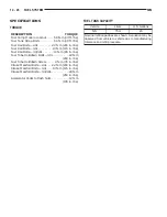
Page 1286: ...Fig 5 Front Crossmember Dimensions 13 6 FRAME AND BUMPERS NS SPECIFICATIONS Continued ...
Page 1287: ...Fig 6 Engine Compartment Top View NS FRAME AND BUMPERS 13 7 SPECIFICATIONS Continued ...
Page 1289: ...Fig 8 Full Vehicle Bottom View NS FRAME AND BUMPERS 13 9 SPECIFICATIONS Continued ...
Page 1291: ...Fig 11 Body Side Openings NS FRAME AND BUMPERS 13 11 SPECIFICATIONS Continued ...
Page 1292: ......
Page 1302: ...FUEL PRESSURE BELOW SPECIFICATIONS 14 8 FUEL SYSTEM NS DIAGNOSIS AND TESTING Continued ...
Page 1304: ...FUEL INJECTOR DIAGNOSIS 14 10 FUEL SYSTEM NS DIAGNOSIS AND TESTING Continued ...
Page 1368: ......
Page 1426: ......
Page 1472: ......
Page 1479: ...Diagnosis Guide NS TRANSAXLE AND POWER TRANSFER UNIT 21 5 DIAGNOSIS AND TESTING Continued ...
Page 1480: ...Diagnosis Guide 21 6 TRANSAXLE AND POWER TRANSFER UNIT NS DIAGNOSIS AND TESTING Continued ...
Page 1481: ...Diagnosis Guide NS TRANSAXLE AND POWER TRANSFER UNIT 21 7 DIAGNOSIS AND TESTING Continued ...
Page 1482: ...Diagnosis Guide 21 8 TRANSAXLE AND POWER TRANSFER UNIT NS DIAGNOSIS AND TESTING Continued ...
Page 1483: ...Diagnosis Guide NS TRANSAXLE AND POWER TRANSFER UNIT 21 9 DIAGNOSIS AND TESTING Continued ...
Page 1484: ...Diagnosis Guide 21 10 TRANSAXLE AND POWER TRANSFER UNIT NS DIAGNOSIS AND TESTING Continued ...
Page 1485: ...Diagnosis Guide NS TRANSAXLE AND POWER TRANSFER UNIT 21 11 DIAGNOSIS AND TESTING Continued ...
Page 1486: ...Diagnosis Guide 21 12 TRANSAXLE AND POWER TRANSFER UNIT NS DIAGNOSIS AND TESTING Continued ...
Page 1656: ......
Page 1723: ...LEAD CORRECTION CHART NS TIRES AND WHEELS 22 5 DIAGNOSIS AND TESTING Continued ...
Page 1726: ...SPECIFICATIONS TIRE SPECIFICATIONS 22 8 TIRES AND WHEELS NS ...
Page 1866: ......
Page 1904: ......
Page 1928: ......