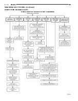


BRAKE DRUM MACHINING
Measure the runout and diameter of the rear brake
using only accurate measuring equipment. There
should be no variation in the drum diameter greater
than 0.090 mm (0.004 inch). Drum runout should not
exceed 0.15 mm (0.006 inch) out of round. If the
drum runout or diameter variation exceed these val-
ues the drum should be refaced. For best results in
eliminating the irregularities that cause brake rough-
ness and surge, the amount of material removed dur-
ing a single cut should be limited to 0.13 mm (0.005
inch). When the entire braking surface has been
cleaned. A final cut of 0.0254 mm (0.001 inch) will
assure a good drum surface providing the equipment
used is capable of the precision required for resurfac-
ing brake drums. Deeper cuts are permissible for the
sole purpose of removing deep score marks. Do not
reface more than 1.52 mm (0.060 inch) over the
standard drum diameter.
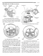
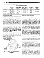
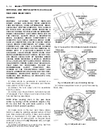
All drums will show markings of maximum allow-
able diameter (Fig. 36). For example, a drum will
have a marking of MAX. DIA. 251.55 mm (9.90 inch).
This marking includes 0.76 mm (0.030 inch) for
allowable drum wear beyond the recommended 1.52
mm (0.060 inch) of drum refacing
BRAKE TUBE REPAIR PROCEDURE
CAUTION: When repairing brake chassis lines or
flex hoses, the correct fasteners must be used to
attach the routing clips or hoses to the front sus-
pension cradle. The fasteners used to attach com-
ponents to the front suspension cradle have an
anti-corrosion coating due to the suspension cradle
being made of aluminum. Only Mopar replacement
fasteners with the required anti-corrosion coating
are to be used if a replacement fastener is required
when installing a brake chassis line or flex hose.
Only double wall 4.75mm (3/16 in.) steel tubing
with Al-rich/ZW-AC alloy coating and the correct tube
nuts are to be used for replacement of a hydraulic
brake tube.
NOTE: On vehicles equipped with traction control,
the primary and secondary hydraulic tubes between
the master cylinder and the hydraulic control unit
are 6 mm (15/64 in.). These tubes are also coated
with the Al-rich/ZW-AC alloy and must be replaced
with tubes having the same anti-corrosion coating.
Be sure the correct tube nuts are used for the
replacement of these hydraulic brake tubes.
Care should be taken when repairing brake tubing,
to be sure the proper bending and flaring tools and
procedures are used, to avoid kinking. Do not route
the tubes against sharp edges, moving components or
into hot areas. All tubes should be properly attached
with recommended retaining clips.
If the primary or secondary brake line from the
master cylinder to the ABS Hydraulic Control Unit,
or the flexible brake lines between the hydraulic con-
trol unit and the proportioning valve require replace-
ment only the original factory brake lines containing
a flexible section can be used. This is required due to
the movement of the front suspension cradle while
the vehicle is in motion.
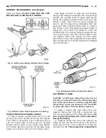
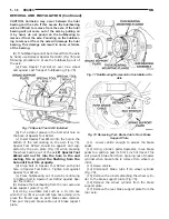
Using Tubing Cutter, Special Tool C-3478-A or
equivalent, cut off damaged seat or tubing (Fig. 37).
Ream out any burrs or rough edges showing on
inside of tubing (Fig. 38). This will make the ends of
tubing square (Fig. 38) and ensure better seating of
ROTOR REFINISHING LIMITS
Braking Rotor
Rotor Thick-
ness
Minimum Rotor
Thickness
Rotor Thick-
ness Variation
Rotor Run
Out*
Rotor Micro
Finish
Front Rotor
23.87-24.13 mm
.939 -.949 in.
22.4 mm
.881 in.
.013 mm
.0005 in.
.08 mm
.003 in.
15-80 RMS
Rear Rotor
12.75-12.25 mm
.502 -.482 in.
11.25 mm
.443 in.
.013 mm
.0005 in.
.08 mm
.003 in.
15-80 RMS
* TIR Total Indicator Reading (Measured On Vehicle)
Fig. 36 Rear Brake Drum Maximum Diameter
Identification
5 - 24
BRAKES
NS
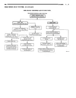
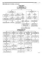
SERVICE PROCEDURES (Continued)
Summary of Contents for 1998 Voyager
Page 8: ...FASTENER IDENTIFICATION NS INTRODUCTION 5 GENERAL INFORMATION Continued ...
Page 9: ...FASTENER STRENGTH 6 INTRODUCTION NS GENERAL INFORMATION Continued ...
Page 11: ...METRIC CONVERSION 8 INTRODUCTION NS GENERAL INFORMATION Continued ...
Page 12: ...TORQUE SPECIFICATIONS NS INTRODUCTION 9 GENERAL INFORMATION Continued ...
Page 16: ......
Page 26: ......
Page 93: ...RED BRAKE WARNING LAMP FUNCTION NS BRAKES 5 11 DIAGNOSIS AND TESTING Continued ...
Page 94: ...POWER BRAKE SYSTEM DIAGNOSTICS 5 12 BRAKES NS DIAGNOSIS AND TESTING Continued ...
Page 95: ...VEHICLE ROAD TEST BRAKE NOISE NS BRAKES 5 13 DIAGNOSIS AND TESTING Continued ...
Page 222: ...COOLING SYSTEM DIAGNOSIS 7 8 COOLING SYSTEM NS DIAGNOSIS AND TESTING Continued ...
Page 223: ...NS COOLING SYSTEM 7 9 DIAGNOSIS AND TESTING Continued ...
Page 224: ...7 10 COOLING SYSTEM NS DIAGNOSIS AND TESTING Continued ...
Page 225: ...NS COOLING SYSTEM 7 11 DIAGNOSIS AND TESTING Continued ...
Page 226: ...7 12 COOLING SYSTEM NS DIAGNOSIS AND TESTING Continued ...
Page 280: ......
Page 286: ......
Page 289: ...CHARGING SYSTEM SCHEMATIC TYPICAL NS CHARGING SYSTEM 8C 3 DIAGNOSIS AND TESTING Continued ...
Page 291: ...CHARGING SYSTEM TEST NS CHARGING SYSTEM 8C 5 DIAGNOSIS AND TESTING Continued ...
Page 292: ...OVERCHARGE TEST 8C 6 CHARGING SYSTEM NS DIAGNOSIS AND TESTING Continued ...
Page 294: ...VOLTAGE DROP TEST 8C 8 CHARGING SYSTEM NS ...
Page 298: ......
Page 372: ......
Page 377: ...NS GS INSTRUMENT PANEL AND SYSTEMS 8E 5 DIAGNOSIS AND TESTING Continued ...
Page 378: ...8E 6 INSTRUMENT PANEL AND SYSTEMS NS GS DIAGNOSIS AND TESTING Continued ...
Page 379: ...NS GS INSTRUMENT PANEL AND SYSTEMS 8E 7 DIAGNOSIS AND TESTING Continued ...
Page 380: ...8E 8 INSTRUMENT PANEL AND SYSTEMS NS GS DIAGNOSIS AND TESTING Continued ...
Page 381: ...NS GS INSTRUMENT PANEL AND SYSTEMS 8E 9 DIAGNOSIS AND TESTING Continued ...
Page 382: ...8E 10 INSTRUMENT PANEL AND SYSTEMS NS GS DIAGNOSIS AND TESTING Continued ...
Page 383: ...NS GS INSTRUMENT PANEL AND SYSTEMS 8E 11 DIAGNOSIS AND TESTING Continued ...
Page 384: ...8E 12 INSTRUMENT PANEL AND SYSTEMS NS GS DIAGNOSIS AND TESTING Continued ...
Page 385: ...NS GS INSTRUMENT PANEL AND SYSTEMS 8E 13 DIAGNOSIS AND TESTING Continued ...
Page 386: ...8E 14 INSTRUMENT PANEL AND SYSTEMS NS GS DIAGNOSIS AND TESTING Continued ...
Page 402: ......
Page 428: ......
Page 440: ......
Page 478: ......
Page 496: ......
Page 504: ......
Page 508: ......
Page 524: ......
Page 542: ......
Page 546: ......
Page 550: ......
Page 559: ...SPECIAL TOOLS SPECIAL TOOL Degausser 6029 NS OVERHEAD CONSOLE 8V 9 ...
Page 560: ......
Page 562: ......
Page 564: ...8W 01 2 8W 01 GENERAL INFORMATION NS GS DESCRIPTION AND OPERATION Continued ...
Page 565: ...NS GS 8W 01 GENERAL INFORMATION 8W 01 3 DESCRIPTION AND OPERATION Continued ...
Page 580: ......
Page 616: ......
Page 660: ......
Page 664: ......
Page 704: ......
Page 718: ......
Page 728: ......
Page 740: ......
Page 744: ......
Page 758: ......
Page 768: ......
Page 784: ......
Page 792: ......
Page 796: ......
Page 800: ......
Page 814: ......
Page 822: ......
Page 826: ......
Page 832: ......
Page 836: ......
Page 840: ......
Page 876: ......
Page 1024: ......
Page 1220: ...Fig 3 Lubrication Lines 9 42 ENGINE NS GS DESCRIPTION AND OPERATION Continued ...
Page 1224: ...ENGINE DIAGNOSIS MECHANICAL CONT 9 46 ENGINE NS GS DIAGNOSIS AND TESTING Continued ...
Page 1286: ...Fig 5 Front Crossmember Dimensions 13 6 FRAME AND BUMPERS NS SPECIFICATIONS Continued ...
Page 1287: ...Fig 6 Engine Compartment Top View NS FRAME AND BUMPERS 13 7 SPECIFICATIONS Continued ...
Page 1289: ...Fig 8 Full Vehicle Bottom View NS FRAME AND BUMPERS 13 9 SPECIFICATIONS Continued ...
Page 1291: ...Fig 11 Body Side Openings NS FRAME AND BUMPERS 13 11 SPECIFICATIONS Continued ...
Page 1292: ......
Page 1302: ...FUEL PRESSURE BELOW SPECIFICATIONS 14 8 FUEL SYSTEM NS DIAGNOSIS AND TESTING Continued ...
Page 1304: ...FUEL INJECTOR DIAGNOSIS 14 10 FUEL SYSTEM NS DIAGNOSIS AND TESTING Continued ...
Page 1368: ......
Page 1426: ......
Page 1472: ......
Page 1479: ...Diagnosis Guide NS TRANSAXLE AND POWER TRANSFER UNIT 21 5 DIAGNOSIS AND TESTING Continued ...
Page 1480: ...Diagnosis Guide 21 6 TRANSAXLE AND POWER TRANSFER UNIT NS DIAGNOSIS AND TESTING Continued ...
Page 1481: ...Diagnosis Guide NS TRANSAXLE AND POWER TRANSFER UNIT 21 7 DIAGNOSIS AND TESTING Continued ...
Page 1482: ...Diagnosis Guide 21 8 TRANSAXLE AND POWER TRANSFER UNIT NS DIAGNOSIS AND TESTING Continued ...
Page 1483: ...Diagnosis Guide NS TRANSAXLE AND POWER TRANSFER UNIT 21 9 DIAGNOSIS AND TESTING Continued ...
Page 1484: ...Diagnosis Guide 21 10 TRANSAXLE AND POWER TRANSFER UNIT NS DIAGNOSIS AND TESTING Continued ...
Page 1485: ...Diagnosis Guide NS TRANSAXLE AND POWER TRANSFER UNIT 21 11 DIAGNOSIS AND TESTING Continued ...
Page 1486: ...Diagnosis Guide 21 12 TRANSAXLE AND POWER TRANSFER UNIT NS DIAGNOSIS AND TESTING Continued ...
Page 1656: ......
Page 1723: ...LEAD CORRECTION CHART NS TIRES AND WHEELS 22 5 DIAGNOSIS AND TESTING Continued ...
Page 1726: ...SPECIFICATIONS TIRE SPECIFICATIONS 22 8 TIRES AND WHEELS NS ...
Page 1866: ......
Page 1904: ......
Page 1928: ......