


FITTING CONNECTING ROD BEARINGS
Engine connecting rod bearing clearances can be
determined by use of Plastigage or equivalent. The
following is the recommended procedure for the use
of Plastigage:
(1) Rotate the crankshaft until the connecting rod
to be checked is at the bottom of its stroke.
(2) Remove oil film from surface to be checked.
Plastigage is soluble in oil.
(3) Place a piece of Plastigage across the entire
width of the bearing shell in the bearing cap approx-
imately 6.35 mm (1/4 in.) off center and away from
the oil hole (Fig. 10). In addition, suspect areas can
be checked by placing plastigage in the suspect area.
(4) Before assembling the rod cap with Plastigage
in place, the crankshaft must be rotated until the
connecting rod being checked starts moving toward
the top of the engine. Only then should the cap be
assembled and torqued to specifications. Do not
rotate the crankshaft while assembling the cap
or the Plastigage may be smeared, giving inac-
curate results.
(5) Remove the bearing cap and compare the width
of the flattened Plastigage (Fig. 10) with the metric
scale provided on the package. Locate the band clos-
est to the same width. This band shows the amount
of clearance in thousandths of a millimeter. Differ-
ences in readings between the ends indicate the
amount of taper present. Record all readings taken.
Refer to Engine Specifications. Plastigage gener-
ally is accompanied by two scales. One scale is
in inches, the other is a metric scale.
(6) Plastigage is available in a variety of clearance
ranges. The 0.025-0.076 mm (.001-.003 in.) is usually
the most appropriate for checking engine bearing
proper specifications.
FITTING MAIN BEARINGS
Refer to the Engine General Information Section
for Measuring Main Bearings. For Crankshaft speci-
fications refer to Crankshaft Specification Table.
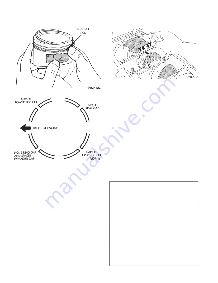
Fig. 8 Installing Side Rail
SIDE RAIL END
Fig. 9 Piston Ring End Gap Position
GAP OF LOWER
SIDE RAIL
NO. 1 RING GAP
GAP OF UPPER
SIDE RAIL
NO. 2 RING GAP AND
SPACER
EXPANDER
GAP
FRONT OF ENGINE
Fig. 10 Measuring Plastigage Width
CRANKSHAFT SPECIFICATION TABLE
Crankshaft End-Play
New Part: 0.09 - 0.24 mm (0.0035 - 0.0094 in.)
Wear Limit: 0.37 mm (0.015 in.)
Main Bearing Clearance
New Part: 0.018 - 0.058 mm (0.0007 - 0.0023 in.)
Connecting Rod Bearing Clearance
New Part: 0.025 - 0.071 mm (0.001 - 0.003 in.)
Wear Limit: 0.075 mm (0.003 in.)
Crankshaft Journal Sizes
Main Bearing Journal Diameter
Standard 60.000
6
0.008 mm (2.3622
6
0.0003 in.)
1 st Undersize 59.975
6
0.008 mm (2.361
6
0.0003
in.)
Connecting Rod Journals
Standard 49.992
6
0.008 mm (1.968
6
0.0003 in.)
1 st Undersize 49.967
6
0.008 mm (1.967
6
0.0003
in.)
JX
2.4L ENGINE
9 - 17
SERVICE PROCEDURES (Continued)
Summary of Contents for 1997 Stratus Convertible LHD
Page 22: ......
Page 186: ......
Page 224: ......
Page 234: ......
Page 237: ...Charging System Schematic Typical JX CHARGING SYSTEM 8C 3 DIAGNOSIS AND TESTING Continued ...
Page 246: ......
Page 320: ......
Page 326: ......
Page 333: ...Fig 9 Wiper Motor Test JX WINDSHIELD WIPERS AND WASHERS 8K 7 DIAGNOSIS AND TESTING Continued ...
Page 358: ......
Page 380: ......
Page 386: ......
Page 396: ......
Page 398: ......
Page 414: ......
Page 464: ......
Page 468: ......
Page 472: ......
Page 496: ......
Page 532: ......
Page 536: ......
Page 572: ......
Page 584: ......
Page 592: ......
Page 598: ......
Page 610: ......
Page 624: ......
Page 628: ......
Page 632: ......
Page 636: ......
Page 640: ......
Page 702: ......
Page 726: ......
Page 733: ...Fig 8 Body Splices JX 8W 95 SPLICE LOCATIONS 8W 95 7 DESCRIPTION AND OPERATION Continued ...
Page 734: ...Fig 9 Rear Body Splices 8W 95 8 8W 95 SPLICE LOCATIONS JX DESCRIPTION AND OPERATION Continued ...
Page 735: ...Fig 10 Door Splices JX 8W 95 SPLICE LOCATIONS 8W 95 9 DESCRIPTION AND OPERATION Continued ...
Page 736: ......
Page 913: ...Fuel Line Adapter 1 4 JX FUEL SYSTEM 14 59 SPECIAL TOOLS Continued ...
Page 914: ......
Page 1033: ...41TE TRANSAXLE HYDRAULIC SCHEMATIC JX TRANSAXLE 21 65 SCHEMATICS AND DIAGRAMS Continued ...
Page 1034: ...41TE TRANSAXLE HYDRAULIC SCHEMATIC 21 66 TRANSAXLE JX SCHEMATICS AND DIAGRAMS Continued ...
Page 1035: ...41TE TRANSAXLE HYDRAULIC SCHEMATIC JX TRANSAXLE 21 67 SCHEMATICS AND DIAGRAMS Continued ...
Page 1036: ...41TE TRANSAXLE HYDRAULIC SCHEMATIC 21 68 TRANSAXLE JX SCHEMATICS AND DIAGRAMS Continued ...
Page 1037: ...41TE TRANSAXLE HYDRAULIC SCHEMATIC JX TRANSAXLE 21 69 SCHEMATICS AND DIAGRAMS Continued ...
Page 1038: ...41TE TRANSAXLE HYDRAULIC SCHEMATIC 21 70 TRANSAXLE JX SCHEMATICS AND DIAGRAMS Continued ...
Page 1039: ...41TE TRANSAXLE HYDRAULIC SCHEMATIC JX TRANSAXLE 21 71 SCHEMATICS AND DIAGRAMS Continued ...
Page 1040: ...41TE TRANSAXLE HYDRAULIC SCHEMATIC 21 72 TRANSAXLE JX SCHEMATICS AND DIAGRAMS Continued ...
Page 1041: ...41TE TRANSAXLE HYDRAULIC SCHEMATIC JX TRANSAXLE 21 73 SCHEMATICS AND DIAGRAMS Continued ...
Page 1042: ...41TE TRANSAXLE HYDRAULIC SCHEMATIC 21 74 TRANSAXLE JX SCHEMATICS AND DIAGRAMS Continued ...
Page 1043: ...41TE TRANSAXLE HYDRAULIC SCHEMATIC JX TRANSAXLE 21 75 SCHEMATICS AND DIAGRAMS Continued ...
Page 1044: ...41TE TRANSAXLE HYDRAULIC SCHEMATIC 21 76 TRANSAXLE JX SCHEMATICS AND DIAGRAMS Continued ...
Page 1045: ...41TE TRANSAXLE HYDRAULIC SCHEMATIC JX TRANSAXLE 21 77 SCHEMATICS AND DIAGRAMS Continued ...
Page 1054: ......
Page 1070: ......
Page 1166: ......
Page 1169: ...JX EMISSION CONTROL SYSTEMS 25 3 DESCRIPTION AND OPERATION Continued ...
Page 1196: ......