


2-2
Matrix StIM/SIM Setup Guide
020-100397-02 Rev. 1 (11-2012)
Section 2: Installation
2.2
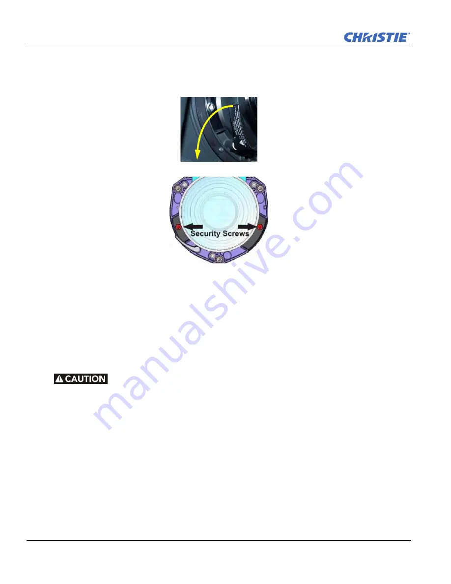
Install the Projection Lens
1. Remove the rear lens cap from the lens. Keep the front lens cap on the lens.
2. Rotate the lens clamp to the OPEN position.
3. Remove and retain the 2 security screws from the lens mount.
4. Align the lens interface plate with the lens mount.
5. Fully insert the assembly straight into the lens mount opening without turning.
NOTICE:
Make sure the
lens is not inserted at an angle as this can cause damage.
6. Rotate the lens clamp to the CLOSED position.
7. Install the security screws removed in step 3.
NOTICE:
Security screws MUST be installed.
8. Remove the front lens cap.
2.3
Lift, Transport and Mount the Projector
•
Mount the projector to a sturdy, flat surface that fits the entire projector. Use all 4 mounting
points to secure the projector to the surface. Use only the Christie approved projector
mounts designed for your projector.
•
Maintain a minimum clearance of 25 cm (10”) around the projector, called a “stay out zone”,
for air circulation and clearance for cable connections to the input panel. Insufficient stay
out zone clearance can cause the projector to overheat during operation and/or place undue
stress on source connections.
The projector should be lifted by 2 people. Use a stable cart to transport the projector. See
6.5 Physical
Specifications
for mounting hole locations, dimensions and other restrictions.
Summary of Contents for Matrix SIM
Page 1: ...Matrix StIM SIM S E T U P G U I D E 020 100397 02 ...
Page 2: ......
Page 3: ...Matrix StIM SIM S E T U P G U I D E 020 100397 02 ...
Page 8: ......
Page 12: ......
Page 20: ......
Page 50: ......
Page 59: ......


