background image

Installation Instructions

AVM1

19

Troubleshooting

1.

Read and review all sections and follow all instructions in
this manual.

2.

Before connecting speakers, verify that all wiring is free
from shorts, opens, crosses or ground problems. Please
verify polarity of speaker wiring (+/-).

3.

After connecting power supply, verify that LED’s have lit on
AVMV panel and on AVxVR card. If there is no power LED
light, verify wiring on the panel and/or card are securely
connected. If there is no light and AC power source is
confirmed; verify that polarity (+/-) wiring is correct with Red
or Ribbed wire as (+) positive. Use front panel soft button
and IR remote control to cycle power On/Off.

4.

If no override page is heard and input audio sources are not
muted during “master-override” page; verify wiring
termination polarity (+/-) to the MO connector and ensure
‘Volt Sens’ POT on rear is adjusted correctly and front MO-
IN ‘orange’ LED lights.

5.

If after power and system terminations have been made and
no audio is detected, ensure volume gains are connected
properly and that all speakers are of the proper impedance
and/or have correct impedance-matching transformers
installed.

6.

If video signal / picture does not appear at AV projector,
please verify LED’s are “on” (Green) at the AVMV front
panel and AVxVR receiver which includes power and signal.
Ensure all CAT5e/RJ454 terminations meet EIA-568B and
terminations of VGA, S-video and Composite video are
made properly at the AV projector. Finally, ensure the AV
Projector and source are transmitting and set to compatible
source and resolution.

NOTE:

Image quality such as Color, Brightness, Focus,

Blurring are most likely adjustments in the projector,
computer and/or video source.

7.

If the remote control does not function please check the
lithium battery.  Also check to ensure direct sunlight or
strong flourescent lights are not interfering.

NOTE:

The IR remote control will not operate beyond 50 feet.

8.

If any of the RF microphones or receivers experience
intermittent noise or drop out please check to ensure
batteries are charged. Please remember RF coverage is
designed to perform without interruption or problem within a
40' x 40' x 10' (typical) room space and may not work well
beyond this depending on room architecture, construction
and line of sight.

9.

If any of the RF microphones or receivers do not show
connection or have continuous flashing Blue LED please
ensure units are properly 'paired'.

10. If after successful wireless install and both TM Teacher

Microphones and SM1 Student Hand held microphone are
confirmed to be performing properly (without noise, drop out
with acceptable coverage throughout the room) and then
after installing the AVxVR transmit module in the RIGHT
SLOT of AVMW with corresponding receiver/ headphones
you now notice intermittent noise or drop out of the
microphones, perform the following steps to change the ID
frequency.

1.

In the power off mode for AVMW module, press both
the power and pairing botton down for 3-5 seconds
until the LED starts a steady RED flash rate.

2.

Press Pairing button on.

3.

Following this procedure, all wireless
microphones should return to normal.
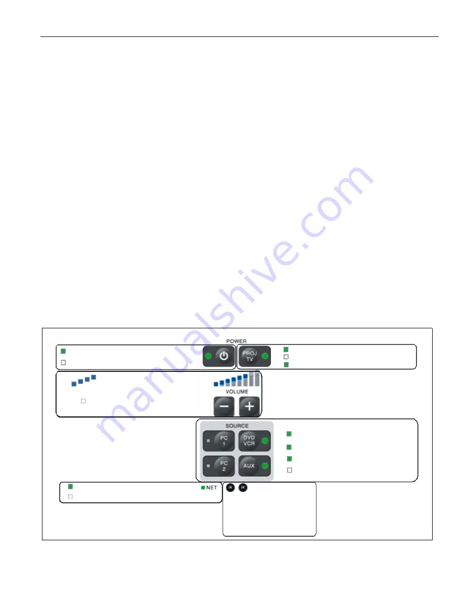
Figure 34

Solid green to indicate “on”

No color to indicate “off”

Solid green to indicate “on”
No color to indicate “off”

Flash green to indicate “processing command”

Solid blue indicates audio volume level

No color indicates no volume or mute

Solid red to indicate “source present”

Flash green to indicate “processing command

Solid green to indicate “active source”

No color to indicate “source not present”

Solid green to indicate “network present”
No color to indicate “network not present”

IrDA infrared LENS

And sensor

Summary of Contents for AVM1

Page 1: ...ções de Instalação Istruzioni di installazione Installatie instructies Instructions d installation Co Pilot Audio Video Control Modules Spanish Product Description German Product Description Portuguese Product Description Italian Product Description Dutch Product Description French Product Description AVM1 ...

Page 2: ...as two blades with one wider than the other A grounding type plug has two blades and a third grounding prong The wide blade or the third prong are provided for your safety If the provided plug does not fit into your outlet consult an electrician for replacement of the obsolete outlet 10 Protect the power cord from being walked on or pinched particularly at plugs convenience receptacles and the poi...

Page 3: ...1 Outlet Boxes Power Supply Bracket and Supporting Hardware DIMENSIONS AVMA AVMA AVMV AVxVR power supply AVRC remote electrical box 3 retro ring 3 decora plate 3 6 32 x 1 2 10 pipe clamp 1 power supply holder 1 10 24 2 3 43 2 87 3 47 2 56 2 75 4 17 ...

Page 4: ...tance 1 to300 AM FM RF andaudiblenoisesuppression Signal tonoiseat85dBandsensitivityat 16dBu OutputtransmissionviaCAT5eUTPcablingupto300 90MwiredperEIA TIA568standard Operationalbandwidthupto350MHz Videodifferential gain phaseat2 Attentuationlossat1dBat300 at1MHz Maximumcapacitanceat20pf footUTPand75 100 impedancematching Powerat5VDCnominalfrom24VDC 2 5Awallsupply AVMA Power Efficiency 80 at 25W 4...

Page 5: ...ave de bocas Chiave a punte aperte Steeksleutel Clé à fourche By Hand A mano Von Hand Com a mão A mano Met de hand À la main Hex Head Wrench Llave de cabeza hexagonal Sechskantschlüssel Chave de cabeça sextavada Chiave esagonale Zeskantsleutel Clé à tête hexagonale Pencil Mark Marcar con lápiz Stiftmarkierung Marcar com lápis Segno a matita Potloodmerkteken Marquage au crayon Drill Hole Perforar B...

Page 6: ...Determine Mounting Locations 1 Take all of the following into consideration when determining mounting locations of projector speakers and input boxes Room size orientation and layout Safety requirements Ceiling and wall types Room lighting Location of whiteboard Location of teacher s desk Students seating arrangement PREPARATION 1 Mount projector according to the installation manuals included with...

Page 7: ...g two 10 24 lock nuts See Figure 2 4 Remove Phoenix connector from power supply Figure 3 5 Extend power supply cord using 18AWG wire making sure it is able to extend from the power source down to the input box location See Figure 3 6 Route extended power supply cord through pipe and down to the input box location See Figure 4 IMPORTANT DO NOT plug power brick cord into power source at this time Ma...

Page 8: ...he AVxVR card to the AVMA and the other to the AVMV 4 Connect retro ring to electrical box outlet by removing two screws from box and using those screws to connect ring to box See Figure 6 Figure 6 5 Remove knockouts from electrical box and route CAT5 cables and remote screen trigger wire through holes IMPORTANT In order to comply with building codes it is highly recommended that a conduit and or ...

Page 9: ...rews to secure AVxVR to retro ring See Figure 9 Figure 9 10 Route cables from devices into corresponding port on AVxVR card See Figure 10 into retro ring 9 Figure 10 3 VGA 3 S Video 3 Composite Video 3 Serial RS232 Projector Connections LED indicator lights ...

Page 10: ... cord Speakers Audio Line Input Device Network Server 6 Route background audio wire through AVMV installation hole 7 Connect retro ring to electrical box outlet by removing two screws from box and using those screws to connect ring to box See Figure 12 Figure 12 8 Remove knockouts to be used from electrical boxes 9 Route cables and wires through holes IMPORTANT In order to comply with building cod...

Page 11: ...0ms attack and release at 3 5 seconds of ALL audio sources See Figure 14 NOTE When MO is activated and Voltage Present is detected on the MO input all audio sources are immediately muted to the amp and speakers NOTE Only the MO audio signal routes to the amp and is broadcast to speakers during MO activation The MO input audio level is adjustable and can be different than the original source materi...

Page 12: ...secure AVMA and AVMV input boxes to the wall See Figure 19 Figure 19 21 Connect audio input devices into AVMV input box See Figure 20 For PC1 use 6 audio connector For PC2 use 6 audio connector For DVD VCR use 10 y adapter and 6 audio connector 22 Connect video input devices into AVMV input box See Figure 21 22 and 23 Use 6 VGA cable for the PC1 and PC2 inputs Use either 6 S Video or 6 composite v...

Page 13: ...Installation Instructions AVM1 13 Figure 20 Figure 21 Audio Connections 6 Audio 3 5mm 10 Audio Y adapter 3 5mm RCA Video Connections 6 VGA 6 S Video 6 Composite Video or ...

Page 14: ...nstructions AVM1 14 Figure 22 Figure 23 Video Connections PC2 connected to document camera or 6 VGA 6 S Video 6 Composite Video Video Connections PC2 connected to desktop monitor 6 VGA 6 S Video 6 Composite Video or ...

Page 15: ...Button Layout AVxRC remote Installation 1 Remove plastic strip at base of AVxRC to engage the battery See Figure 25 Figure 25 2 Battery should be ready to operate Replacing the AVxRC Battery NOTE The AVxRC is shipped with a 3V lithium battery already installed If the battery needs to be replaced perform the following steps 1 Turn the AVxRC remote over on its back See Figure 26 2 Pull tab towards t...

Page 16: ...or Ultimate Editions IIS 7 5 Windows Server 2008 R2 and Windows 7 IMPORTANT Microsoft net Framework version 3 5 must be installed It is available for download at http go microsoft com fwlink LinkID 124150 IMPORTANT Make sure correct version of Framework is installed for the system being used Each version of Framework is only compatible with certain operating systems IMPORTANT Make sure the Microso...

Page 17: ...install the CoPilot service Extract files from site files zip and save into C inetpub wwwroot Create copilot directory and save files there Right click on My Computer and select Manage The computer management snap in will come up Expand the Services and Applications node then the Internet Information Services node then the Web Sites folder See Figure 30 Right click on the default web site node and...

Page 18: ...run to ensure that the system is fully operation at the end of installation Refer to Figures 33 and 34 for button functionality on AVMA in order to perform tests 1 Power On Off Check 2 Audio Volume Check 3 Video Check 4 Override Check 5 Fire Check 6 Security Check 7 Screen Lowering Raising Check 8 Device Checks 9 Remote Check 10 Network Check Room Panel User Admin Room Admin System Administration ...

Page 19: ...ol does not function please check the lithium battery Also check to ensure direct sunlight or strong flourescent lights are not interfering NOTE The IR remote control will not operate beyond 50 feet 8 If any of the RF microphones or receivers experience intermittent noise or drop out please check to ensure batteries are charged Please remember RF coverage is designed to perform without interruptio...

Page 20: ...AVM1 Installation Instructions 20 MAC Address Labels Worksheet Room MAC Label Room Description 1 2 3 4 5 6 7 8 9 10 11 12 13 14 15 16 17 18 19 20 21 22 ...

Page 21: ...Installation Instructions AVM1 21 MAC Address Labels Worksheet continued Room MAC Label Room Description 23 24 25 26 27 28 29 30 31 32 33 34 35 36 37 38 39 40 41 42 43 44 ...

Page 22: ...AVM1 Installation Instructions 22 MAC Address Labels Worksheet continued Room MAC Label Room Description 45 46 47 48 49 50 51 52 53 54 55 56 57 58 59 60 61 62 63 64 65 66 ...

Page 23: ...Installation Instructions AVM1 23 ...

Page 24: ...130 5611 ZB EINDHOVEN The Netherlands P 31 0 40 2668620 F 31 0 40 2668615 Asia Pacific A Office No 1 on 12 F Shatin Galleria 18 24 Shan Mei Street Fotan Shatin Hong Kong P 852 2145 4099 F 852 2145 4477 Chief Manufacturing a products division of Milestone AV Technologies 8803 002014 Rev00 2010 Milestone AV Technologies a Duchossois Group Company www chiefmfg com 08 10 ...

Reviews: