


FEB 2017
CMT 130 Book Trimmer
4-5
4. Repair/Adjustment Procedures
14. Place 4 knife bolts into the 4 available holes
in the knife and use the T-handle wrench to
secure them as shown in Figure 4-7.
15. Turn the lifter handles counterclockwise and
remove the lifter from the machine.
16. Place 2 knife bolts into the holes from which
the knife lifter handles were removed. Use
the T-handle wrench to secure them.
Viewed through the inspection holes, the
blade should be inserted against the stops.
Once the knife has been installed, the cutting
depth must be adjusted (REP 4.3 Knife Depth
Adjustment).
CAUTION
The knives must be adjusted after every knife
change. Improper knife adjustment may cause
damage to the machine.
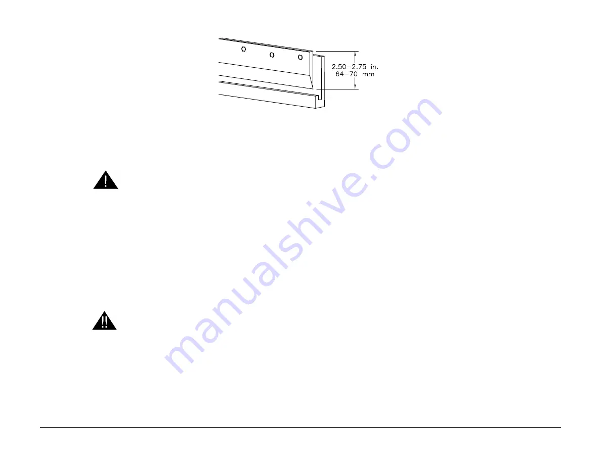
Knife Sharpening Amount
A total of 1/4" (6.4mm) of material may be re-
moved due to repeated sharpenings. Beyond
this, the machine will not cut fully through a
book.
The knife must
not
be sharpened to less than a
knife height of 2.50 in. (63.5 mm) as shown in
Figure 4-8.
WARNING
Knives can be very dangerous unless safety
precautions are observed and extreme care
is taken when handling knives. Keep han-
dling of unprotected knives to an absolute
minimum. Keep knives in scabbard when at
all possible. Warn people of any unprotected
knife.
Figure 4-8. Knife Height Range
Summary of Contents for CMT-130
Page 80: ...FEB 2017 2 Status Indicator RAPs 2 70 CMT 130 Book Trimmer NOTES...
Page 112: ...FEB 2017 4 Repair Adjustment Procedures 4 28 CMT 130 Book Trimmer NOTES...
Page 166: ...FEB 2017 5 Parts List 5 54 CMT 130 Book Trimmer PL 5 53 Std Hand Feed Elec EE 3342...
Page 198: ...FEB 2017 6 General Procedures Information 6 26 CMT 130 Book Trimmer NOTES...
Page 200: ...FEB 2017 7 Wiring Data 7 2 CMT 130 Book Trimmer WD 7 1 Schematic 230 VAC E 3307 1 1 9...
Page 201: ...FEB 2017 CMT 130 Book Trimmer 7 3 7 Wiring Data WD 7 2 Schematic 120 VAC E 3307 1 2 9...
Page 202: ...FEB 2017 7 Wiring Data 7 4 CMT 130 Book Trimmer WD 7 3 Schematic 27 VAC E 3307 1 3 9...
Page 203: ...FEB 2017 CMT 130 Book Trimmer 7 5 7 Wiring Data WD 7 4 Schematic 18 VAC E 3307 1 4 9...
Page 204: ...FEB 2017 7 Wiring Data 7 6 CMT 130 Book Trimmer WD 7 5 Schematic 9 VAC E 3307 1 5 9...
Page 205: ...FEB 2017 CMT 130 Book Trimmer 7 7 7 Wiring Data WD 7 6 Schematic 35 VDC E 3307 1 6 9...
Page 206: ...FEB 2017 7 Wiring Data 7 8 CMT 130 Book Trimmer WD 7 7 Schematic 24 VDC E 3307 1 7 9...
Page 207: ...FEB 2017 CMT 130 Book Trimmer 7 9 7 Wiring Data WD 7 8 Schematic 15 VDC E 3307 1 8 9...
Page 208: ...FEB 2017 7 Wiring Data 7 10 CMT 130 Book Trimmer WD 7 9 Schematic 5 VDC E 3307 1 9 9...
Page 209: ...FEB 2017 CMT 130 Book Trimmer 7 11 7 Wiring Data WD 7 10 Plug Connections to PWB EE 2939 2...
Page 210: ...FEB 2017 7 Wiring Data 7 12 CMT 130 Book Trimmer WD 7 11 Schematic Elevator EE 2980 1...
Page 211: ...FEB 2017 CMT 130 Book Trimmer 7 13 7 Wiring Data WD 7 12 Schematic Tilt Conv EE 2993 3...
Page 212: ...FEB 2017 7 Wiring Data 7 14 CMT 130 Book Trimmer WD 7 13 Schematic Long In Feed EE 2985 1...
Page 213: ...FEB 2017 CMT 130 Book Trimmer 7 15 7 Wiring Data WD 7 14 Schematic Std In Feed EE 2985 1...
Page 214: ...FEB 2017 7 Wiring Data 7 16 CMT 130 Book Trimmer WD 7 15 Schematic Exit Conv EE 2979 3...


