53
Section 4 - Owner Serviceable Items
1. Measure the distance from the edge of the bearing
assembly mounting brackets to the bearing
assemblies to serve as a reference point for
subsequent adjustments.
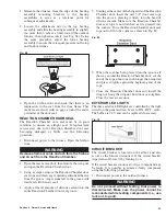
2. Loosen the adjustment nut on the top bearing
assembly and slide the bearing assembly in slightly
(no more than 3 mm at a time) toward the outdoor
furnace; then tighten securely (see Fig. 68). Using
the same procedure, adjust the lower bearing
assembly to ensure there is equal pressure on the top
and bottom latches.
Fig. 68
2. Open the firebox door and check that there is an
impression in the seal from the door frame. This
mark must extend, with no gaps, around the entire
perimeter of the door seal.
REACTION CHAMBER DOOR SEAL
The Reaction Chamber door seal must be in good
condition to ensure an airtight seal. If replacement
is necessary due to the Reaction Chamber door seal
becoming damaged or brittle, use the following
procedure:
1. Disconnect power to the furnace. Open the firebox
door.
WARNING
Remove all wood, coals and ash from the firebox
and all ash from the Reaction Chamber.
2. Open the rear access door; then remove the wing nut
and open the Reaction Chamber door.
3. Using a scraper, remove the Reaction Chamber door
seal rope and clean any remaining silicone adhesive
from the groove. Any residue left in the groove will
interfere with the new seal.
4. Apply a liberal amount of silicone sealant into the
entire Reaction Chamber door seal groove.
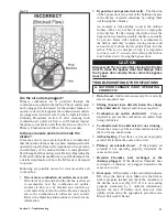
5. Starting at the center of the hinge side of the Reaction
Chamber door, insert the new 3/4" door seal rope
into the groove, pressing it firmly into the bead of
silicone sealant. Make sure the Reaction Chamber
door seal rope is not stretched as it is pressed into
the corners. Force the Reaction Chamber door seal
rope out to fill in the corners as shown in Fig. 69.
Fig. 69
6. When the seal has been pressed into the groove all
the way around the Reaction Chamber door, cut the
end of the rope about one inch longer than required
and press it tightly against the beginning end of the
rope.
7. Close the Reaction Chamber door and install the
wing nut. Snug the wing nut, but do not over-tighten.
Close the rear access door.
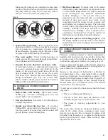
EXTERIOR LED LIGHTS
The three exterior LED lights are controlled by the light
switch on the panel and can be set to ON - OFF - Auto.
The bulbs are 24 V and can be replaced if necessary.
Fig. 70
CIRCUIT BREAKER
The circuit breaker is located on the airbox and also
serves as the furnace disconnect. If the circuit breaker
trips (turns off), reset it by turning it on.
If the circuit breaker continues to trip, a component may
be faulty. It is possible to isolate a faulty component
using the following procedure.
1. Disconnect power to the outdoor furnace.
WARNING
Do not proceed without testing that power is
disconnected. Make sure the power cannot be
reconnected while testing components (i.e., use
lock out, tag out).
Summary of Contents for e-Classic 1450 IR
Page 17: ...15 Section 1 Outdoor Furnace Installation...
Page 29: ...27 Section 1 Outdoor Furnace Installation Fig 30 Fig 31...
Page 30: ...28 Section 1 Outdoor Furnace Installation Fig 32 Fig 33...
Page 66: ...64 E CLASSIC 1450 WIRING DIAGRAM Section 6 General Information...
Page 67: ...65 Section 6 General Information E CLASSIC 1450 WIRING DIAGRAM OPTIONAL POWER IGNITION...
Page 69: ...67 NOTES...
Page 70: ...68 NOTES...
Page 71: ...69 NOTES...


