background image

50

3.  If the pH level is between 6.5 and 8.0 and there are 

no other known water quality problems, then the 

outdoor furnace may be filled with this water.

4.  If the water to be used to fill the outdoor furnace has 

a pH level of less than 6.5 or greater than 8, a sample 

of the water should be sent to a water quality test 

lab for recommended treatment, the water should 

be conditioned, or water should be supplied from a 

different source.

Corrosion Inhibitor Plus™ and Initial 

Treatment

Central Boiler Corrosion Inhibitor Plus™ (p/n 1650) 

gives optimum protection when it is used to initially 

treat the water and is then maintained at proper levels. 

The initial nitrite level target is 20 drops by nitrite 

test, but 20 to 30 drops is acceptable. Do not exceed 

treatment of higher than 30 drops by nitrite test.
The recommended initial treatment rate for the outdoor 

furnace is specified by units. One unit of the Corrosion 

Inhibitor Plus™ is a 1-gallon (3.78-liter) container. The 

normal rate for the initial treatment is 2 units.

NOTE:  If  the  system  has  a  larger  than  normal 

water capacity, more Corrosion Inhibitor Plus™ 

should be added at a recommended rate of one 

unit per 180 gallons (681 liters) of water.

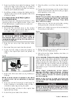
1. Add the recommended amount of Corrosion 

Inhibitor Plus™ through the vent pipe at the top of 

the outdoor furnace.

2.  Immediately fill the outdoor furnace to 1 inch (2.5 

cm) below the FULL level mark on the sight gauge.

3.  Start the pump(s) and circulate water for 24 hours.

Testing Treated Water in the Outdoor 

Furnace

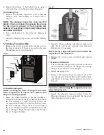
1.  To obtain a system water sample, it will be necessary 

to bend the sight gauge tube away from the outdoor 

furnace. Before collecting the sample, open the valve 

and drain about a quart of water from the sight gauge 

tube; then carefully fill the sample container without 

contaminating the sample. Be sure to properly 

install the sight gauge tube and close the valve 

when finished. The water in the sight gauge valve 

and tube will drain when the valve is closed.

CAUTION

The  water  in  the  sight  gauge  may  be  hot.  Use 

caution when obtaining a sample.

2.  If no antifreeze is present in the water, use Test Kit 

(p/n 405). If antifreeze has been added to the water, 

use Test Kit (p/n 597).

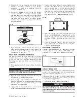
3.  Dip the pH test strip from the test kit in the water 

sample. Shake excess water off the test strip. 

Compare the color of the test strip to the chart 

provided to determine pH level. The pH of the water 

should now be between 8.0 and 9.5.

4.  Rinse and fill the sample tube to the 25 mL mark 

with treated water from the outdoor furnace.

5.  Add 25 drops of Sulfuric Acid (p/n 404) to the water 

sample and swirl to mix.

WARNING

Sulfuric Acid is a corrosive acid. Handle carefully. 

Carefully  read  and  follow  precautions  on  test 

chemical labels. Keep test chemicals away from 

children. Safely dispose of tested samples.

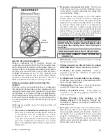
6.  Using the dropper, add Permanganate Reagent (p/n 

403) one drop at a time, swirling the water and 

counting each drop, until the color changes from 

colorless to a faint pink that persists for at least one 

minute.

NOTE:  Always  hold  the  dropper  in  a  vertical 

position to ensure proper droplet size.

7.  If the nitrite level is not at least 20 drops by nitrite 

test, add 1/4 unit of Corrosion Inhibitor Plus™ (p/n 

1650); then circulate water for 24 hours and repeat 

procedure, as needed, to achieve a nitrite level of at 

least 20 drops by nitrite test. 

8.  Do not exceed treatment of higher than 30 drops by 

the nitrite test. If the test requires more than 30 drops, 

dilute the water by draining water from the system 

until the water level just reaches the bottom of the 

sight gauge. Then perform steps 2-3 from Corrosion 

Inhibitor Plus™ and Initial Treatment and steps 1-9 

from Testing Treated Water in the Outdoor Furnace.

CAUTION

Completely clean out the firebox before draining 

water from the outdoor furnace. 

9.  After  the  proper  nitrite  level  has  been  obtained, 

check pH to make sure it is between 8 and 9.5.

After initial treatment, the maintenance nitrite level 

target is 15 drops by nitrite test, but 15 to 30 drops is 

acceptable. One drop of permanganate reagent equals 

approximately 100 ppm. 

System Maintenance

The pH and nitrite levels of the water, once treated, 

should remain stable as long as water is not added to 

the outdoor furnace. If water is added to the outdoor 

furnace and/or system, the system water should be 

tested and Corrosion Inhibitor Plus™ should be added 

(if necessary) to maintain the recommended level of 

protection.

Section 3 - Maintenance

Summary of Contents for e-Classic 1450 IR

Page 1: ...personal injury or loss of life Do not store or use gasoline or other flammable vapors and liquids in the vicinity of this or any other appliance WHAT TO DO IF YOU SMELL GAS Do not try to light any a...

Page 2: ...re determined under the same test conditions using higher heating value lower heating value and annual fuel utilization efficiency AFUE This heater meets the 2015 U S Environmental Protection Agency s...

Page 3: ...Direct Circulation Baseboard Installation 25 Radiant Floor System Installations 26 Pool and or Hot Tub Heating 29 FILLING OUTDOOR FURNACE WITH WATER AND PURGING AIR 30 SECTION 2 OPERATING INSTRUCTION...

Page 4: ...ce water temperature is below 100 F and or there is no charcoal base left in the firebox E Classic Refueling Tips Following a few easy tips when you re refilling your E Classic with wood will help to...

Page 5: ...tallation Section 2 Operating Instructions Section 3 Maintenance Section 4 Owner Serviceable Items Section 5 Troubleshooting Section 6 General Information Anyone owning or operating this outdoor furna...

Page 6: ...he electrical power to the outdoor furnace before replacing an electrical component WARNING Should overheating occur or the gas supply fail to shut off do not turn off or disconnect the electrical sup...

Page 7: ...ir dried seasoned hardwoods as compared to softwoods or to green or freshly but hardwoods DO NOT BURN any wood that is not clean wood unseasoned wood garbage tires lawn clippings leaves brush trimming...

Page 8: ...the hot supply and return water lines and insulation Be sure to maintain the required clearances to combustibles and recommended maintenance clearances ThermoPEX pre insulated piping is recommended f...

Page 9: ...damaged If something is located within the fall zone and cannot be removed guy wires or braces may need to be installed to prevent a falling chimney from causing damage see Fig 2 NOTE If more than thr...

Page 10: ...the existing heat emitter s To prevent freezing if the outdoor furnace is not fired for extended time periods or if lengthy power outages are anticipated during cold weather a nontoxic propylene glyco...

Page 11: ...the ground rod is below the ground surface 2 Route the ground wire from the ground rod under the outdoor furnace base and over to the frame of the outdoor furnace 3 Secure the ground terminal with a...

Page 12: ...14 2 two wires plus ground underground rated wire should supply the outdoor furnace with electricity A heavier gauge wire may be needed if the run is over 200 feet 61 meters Check local codes and requ...

Page 13: ...nnection must be tested for leaks before placing the appliance in operation HIGH ALTITUDE INSTALLATIONS High altitude derating instructions are included with the Gas fired Wood Ignition Burner Kit CIR...

Page 14: ...r furnace is 10A 120VAC and 60Hz A The pump motor must be installed in a horizontal position B The junction box must not be located below the pump motor see Fig 10 If necessary remove the four screws...

Page 15: ...bove the pump should be adequate for systems with higher resistance e g longer loops with other fittings elbows heat exchangers For systems with low resistance e g short loops larger diameter pipes an...

Page 16: ...valve A thermostatic valve must be installed on each set of supply and return lines in the system to maintain the outdoor furnace water temperature above 150 F 65 C Operating the outdoor furnace with...

Page 17: ...15 Section 1 Outdoor Furnace Installation...

Page 18: ...r thermostatic mixing valve is to be installed in the hot water outlet from the water heater Install a tee in a fitting on the top of the water heater see Fig 18 for the hot water heat exchanger NOTE...

Page 19: ...heat exchanger it should be mounted in the center without gaps on the sides that would allow air to flow around the heat exchanger All air must be directed through the face of the exchanger Air flow d...

Page 20: ...85 F 85 C minimum NOTE On multi speed fans cap and tape off any extra wires NOTE Installer must comply with all applicable codes and regulations NOTE This configuration allows use of a 24 volt thermos...

Page 21: ...ine between the outdoor furnace and thermostatic valve Outdoor furnace water temperature setpoint should be set at 185 F minimum NOTE Forced Air System and Water Heater Heat Exchanger Components p n 1...

Page 22: ...operate if the outdoor furnace is out of fuel Refer to Fig 22 for one possible arrangement 2 An alternative method is to install a line voltage thermostat to control the blower on the forced air furn...

Page 23: ...need for manifolds for mounting of up to two pumps on the outdoor furnace NOTE Pump s may be installed on the outdoor furnace or inside the building NOTE If a Taco 014 pump is used the pump should be...

Page 24: ...be water baseboard heaters or panel radiators 2 A water to air heat exchanger with a thermostatic ally controlled fan can be installed in the lower part of the building being heated Fig 24 This can in...

Page 25: ...ely 165 F 74 C of water temperature transfer The temperature controller on the outdoor furnace may be adjusted to allow the outdoor furnace to reach water temperatures up to 195 F 91 C Each system wil...

Page 26: ...urge the air from the indoor system by closing the valves on the outdoor furnace then pressurize the indoor system with water from the domestic water line CAUTION Do not apply more pressure to the ind...

Page 27: ...ig 27 and 28 illustrate direct circulation baseboard installation examples This horizontal assembly must not exceed a height of 4 inches 10 cm above top of water heater NOTE Outdoor furnace water temp...

Page 28: ...Fig 29 through Fig 32 The spacing of each circuit is 12 30 5 cm between pipes The water circulates in opposite directions to provide an even distribution of heat The mixing valve regulates the temper...

Page 29: ...27 Section 1 Outdoor Furnace Installation Fig 30 Fig 31...

Page 30: ...28 Section 1 Outdoor Furnace Installation Fig 32 Fig 33...

Page 31: ...may cause severe personal injury death or substantial property damage CAUTION Do not operate the outdoor furnace frequently or for extended periods of time with the water temperature below 150 F 65 C...

Page 32: ...eel 1 Connect the male end of garden hose A to valve 1 using the backflow preventer and two 3 4 female hose x 3 4 male pipe adapters p n 4928 Connect the female end of the garden hose to valve 2 2 Clo...

Page 33: ...t 17 Refer to Firing the Outdoor Furnace to fire up the outdoor furnace CAUTION Be sure the outdoor furnace is filled with water before firing Never fire the outdoor furnace when the water level is mo...

Page 34: ...the firebox and increased wood consumption Increased moisture in the firebox can result in corrosion Unseasoned wood causes reduced performance lower combustion rates and lower heat output The full he...

Page 35: ...lection and Preparation in the Introduction In order for wood to burn the moisture in the wood must first be evaporated boiled off The more moisture there is in the wood the more energy it will consum...

Page 36: ...become familiar with your particular conditions This will allow you to identify cause and effect in a variety of circumstances and what works best for your conditions CAUTION Do not burn plastic garba...

Page 37: ...pull the bypass door handle toward the front of the outdoor furnace and push down to close the bypass door 8 After the water temperature is above 150 F 66 C proceed to Adding Heat Load Cold Start Fir...

Page 38: ...operation Leaving the bypass door open during operation may cause damage to components of the outdoor furnace and may cause creosote buildup that can prevent the bypass door from sealing properly NOT...

Page 39: ...ble as the firebox door is opened because smoke and hot gases escaping through the firebox door opening could ignite From a safe distance observe the fuel load WARNING Use extreme care when adding woo...

Page 40: ...e firebox door is open uncontrolled amounts of air entering the firebox can accelerate combustion It is very important to leave the bypass door open for 15 seconds after closing and latching the fireb...

Page 41: ...the firebox and air channels will not dry NO DRYING Very little radiant heat to dry air channels High humidity Reloading at this level can restrict airflow and create excessive coals or too deep of a...

Page 42: ...ly until interval for your application can be determined D When new after three months then every six months thereafter F Frequency will vary depending on heat load requirements type of wood used and...

Page 43: ...ow burning fire As a result cresote residue accumulates on the flue lining When ignited this creosote makes an extremely hot fire The chimney connector and chimney should be inspected at least twice m...

Page 44: ...e of ash 3 Remove any heavy or solidified ash CAUTION Always wear the appropriate personal protective gear when cleaning ash from the firebox and the Reaction Chamber 4 Disposal of ashes Ashes should...

Page 45: ...g out Leaking air caused by an improperly fitting cover can cause corrosion Fig 49 3 7 Heat Exchangers 1 Press the Power button on the FireStar controller to turn it off CAUTION Be sure to turn off th...

Page 46: ...t be tipped back as shown before lifting it out Thermocouple Fig 53 5 Install the refactory end cap by tipping it forward before setting it in place Close the Reaction Chamber door and install the win...

Page 47: ...d without testing that power is disconnected 2 Open the rear access door then inspect the combustion air fan inlet screen and fan wheel and clean if necessary Make sure the air intake is clean and not...

Page 48: ...tighten the hose clamp 8 Connect the power leads to the solenoid 9 Close the airbox cover then close the rear access door 10 Connect the electrical power to the outdoor furnace at the main power sour...

Page 49: ...shown in Fig 61 Use a hoe to pull the ash to the rear of the furnace then use a small shovel to remove all of the ash and deposits from the Reaction Chamber Take care not to damage or move the firebri...

Page 50: ...chamber then insert the heat exchanger scraper and drop it down the chamber while holding on to the second chain Once the heat exchanger scraper drops to the bottom of the heat exchanger drop the seco...

Page 51: ...el that is too high the results should be verified using a new test kit The pH test strips and Permanganate Reagent each have a varying shelf life that can affect their accuracy Test kits should be st...

Page 52: ...05 If antifreeze has been added to the water use Test Kit p n 597 3 Dip the pH test strip from the test kit in the water sample Shake excess water off the test strip Compare the color of the test stri...

Page 53: ...m the furnace remove the plug from the unused supply port to prevent damage from water freezing in the supply port pipe Fig 64 Flushing the System If the system water is brown or orange it is an indic...

Page 54: ...etely fill them When the start of the seal is reached cut the end of the seal about an inch longer than required at an angle that matches the starting end then remove the seal from the groove Fig 66 3...

Page 55: ...ere with the new seal 4 Apply a liberal amount of silicone sealant into the entire Reaction Chamber door seal groove 5 Starting at the center of the hinge side of the Reaction Chamber door insert the...

Page 56: ...that power is disconnected Make sure the power cannot be reconnected while servicing the solenoids i e use lock out tag out 2 Open the airbox cover located at the rear of the outdoor furnace NOTE Smo...

Page 57: ...the alignment hole in the refractory modules THERMOCOUPLE 1 Disconnect power to the outdoor furnace WARNING Do not proceed without testing that power is disconnected Make sure the power cannot be rec...

Page 58: ...will help to dry out the wood loaded on top of those pieces Is the coal bed the correct depth One to three inches 2 5 to 7 5 cm of glowing coals are needed to optimize the operation of the outdoor fur...

Page 59: ...he outdoor furnace with a very hot bed of coals or a raging fire in the firebox If after closing the firebox door the bypass door is closed too quickly the fire can actually be put out Gases will cont...

Page 60: ...essure in the chimney may be incorrect and adding more chimney sections may be required However due to many variables even if exhaust does not come out from around the cover the chimney might still no...

Page 61: ...plies power to the outdoor furnace check that it is on 3 Circuit breaker on airbox off Check that the circuit breaker switch on the airbox is on If the circuit breaker has tripped determine the cause...

Page 62: ...al If firebox door does not close tightly adjust using the appropriate procedure see Owner Serviceable Items Fig 80 NOTE If the outdoor furnace is operated with the door open the firebox door seal wil...

Page 63: ...rete slab up to temperature the first time will take a considerable amount of time and wood once warm wood consumption will be reduced if the concrete slab and building are insulated properly The foll...

Page 64: ...als are needed to optimize the operation of the outdoor furnace 7 Wood contains too much moisture Use correctly sized seasoned wood I CORROSION IS PRESENT Corrosion in the firebox can occur when the o...

Page 65: ...plug from the unused supply port to prevent damage from water freezing 1 1 4 1 1 4 1 1 4 Drain Valve Plug NOTICE For use with aluminum or copper conductors p n 7000039 SECTION 6 GENERAL INFORMATION M...

Page 66: ...64 E CLASSIC 1450 WIRING DIAGRAM Section 6 General Information...

Page 67: ...65 Section 6 General Information E CLASSIC 1450 WIRING DIAGRAM OPTIONAL POWER IGNITION...

Page 68: ...OOD Wood that has been dried to less than 25 moisture content and kept out of the weather to maintain that moisture content SECONDARY AIR CHARGE TUBE Tube located on the bottom of the firebox that pro...

Page 69: ...67 NOTES...

Page 70: ...68 NOTES...

Page 71: ...69 NOTES...

Page 72: ...r gaskets seals heat shields paint charge tube grates combustors aquastats actuators heat refractory and firebrick Parts that are factory installed by Central Boiler but are manufactured by others may...

Reviews: