49
Section 3 - Maintenance
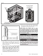
8. Combustion Air Outlets/Air Channel
Plates
1. Slide each of the four corner sections up and remove
any ash or deposits from behind them. With access
from the rear corners of the firebox, remove any ash
or debris from the permanent air channel in the rear
of the firebox.
2. Mark the location of each air channel plate; then
remove the acorn nuts securing the RH and LH side
air channel plates and remove the plates. Remove
any ash or deposits from behind the air channel
plates in the wall of the firebox.
3. Using a screwdriver or similar tool, clean out each
combustion air outlet in the air channel plates and
the corner sections. Make sure any debris or buildup
on the back side of the plates and corner sections is
removed.
4. Replace the corner sections by sliding them down
in each corner of the firebox. Replace the side air
channel plates, starting with the center section, then
the front section and lastly the rear section. Replace
the acorn nuts and tighten securely.
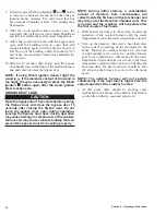
5. Press the Power button to turn the FireStar
controller on.
6. With the firebox door open, temporarily hold the
door switch in. Air should blow into the firebox
from each of the combustion air outlets. Feel with
your hand to ensure air is coming out of each outlet.
If air is not blowing through an outlet, determine
and correct the cause.
7. Refer to the Firing the Outdoor Furnace section for
initial start-up procedures.
WATER QUALITY AND MAINTENANCE
An important part of outdoor furnace maintenance
is controlling the quality of the water in the outdoor
furnace. Central Boiler supplies a pH test strip and a
nitrite test kit with each new outdoor furnace.
Water Test Kits and Test Results
It is very important to keep record of water test results
(include the date, pH and nitrite level). If subsequent
water tests indicate a pH that is too low and/or a nitrite
level that is too high, the results should be verified
using a new test kit.
The pH test strips and Permanganate Reagent each have
a varying shelf life that can affect their accuracy. Test
kits should be stored in a dry area at room temperature
to obtain maximum accuracy over a longer period of
time.
The pH of the water in the outdoor furnace will not
decrease unless fresh water is added to the furnace. The
nitrite level of the water in the outdoor furnace will not
increase unless Corrosion Inhibitor Plus™ is added. For
example, if a water test in the fall of the year indicates
a pH of 8.5 and a nitrite level of 20 drops by nitrite
test (2000 ppm) and no water or Corrosion Inhibitor
Plus™ is added, a water test the following spring must
indicate a pH of at least 8.5 and a nitrite level of no
more than 20 drops by nitrite test (or slightly less, due
to evaporation).
If the test indicates a significantly lower pH level or
higher nitrite level, perform another test with a new test
kit to verify the results. If the results are +10% different
using a new test kit, either water or Corrosion Inhibitor
Plus™ has been added to the system.
If a test is conducted and verified that indicates a high
pH (above 9.5) and/or nitrite level (above 30 drops),
DO NOT ADD MORE CORROSION INHIBITOR
PLUS™. Adding Corrosion Inhibitor Plus™ increases
nitrite and pH levels.
The outdoor furnace should be drained until the water
in the sight gauge reaches the bottom of the sight gauge;
then add fresh water until it is 1 inch (2,5 cm) below the
FULL mark on the sight gauge. Circulate the water for
24 hours and test the water again.
Testing Supply Water
Before filling the outdoor furnace with water, test a
sample of the supply water that will be used to fill the
outdoor furnace (softened water is recommended).
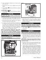
1. Collect a small sample of the water to be used to fill
the outdoor furnace in a clean container.
2. Dip the pH test strip from the test kit in the water
sample. Shake excess water off the test strip.
Compare the color of the test strip to the chart
provided to determine pH level.
Summary of Contents for e-Classic 1450 IR
Page 17: ...15 Section 1 Outdoor Furnace Installation...
Page 29: ...27 Section 1 Outdoor Furnace Installation Fig 30 Fig 31...
Page 30: ...28 Section 1 Outdoor Furnace Installation Fig 32 Fig 33...
Page 66: ...64 E CLASSIC 1450 WIRING DIAGRAM Section 6 General Information...
Page 67: ...65 Section 6 General Information E CLASSIC 1450 WIRING DIAGRAM OPTIONAL POWER IGNITION...
Page 69: ...67 NOTES...
Page 70: ...68 NOTES...
Page 71: ...69 NOTES...


