45
Section 3 - Maintenance
NOTE: Be aware that the hotter the fire, the less
creosote is deposited, so weekly cleaning may be
necessary in mild weather, even though monthly
cleaning may be enough in coldest months.
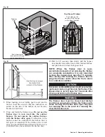
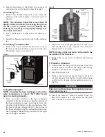
3-10. Combustion Air Outlets
Primary combustion air enters the firebox through
the combustion air outlets located on the sides and in
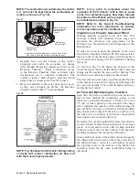
the front and back corners (Fig. 54). It is essential to
the operation of the outdoor furnace that these outlets
remain unobstructed. Clean the combustion air outlets
before they become plugged. The corner sections can be
removed for cleaning by sliding them up. The side air
channels can be removed for cleaning by removing the
acorn nuts. Make sure to thoroughly remove all ash and
deposits from behind the corner and side air channels.
Fig. 54
© 2012 Central Boiler
Combustion
Air Outlets
Slide Up
to Remove
Pull Out
to Remove
3-11. Combustion Air Fan
1. Disconnect power to the outdoor furnace.
WARNING
Do not proceed without testing that power is
disconnected.
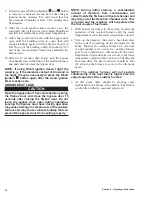
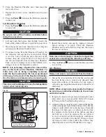
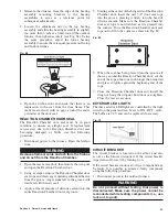
2. Open the rear access door; then inspect the
combustion air fan inlet screen and fan wheel and
clean if necessary. Make sure the air intake is clean
and not obstructed.
Fig. 55
3. Connect power to the furnace.
NOTE: At the end of each heating season, oil
the combustion fan bearings using the following
procedure.
1. Remove the bolts securing the combustion fan and
remove the combustion fan.
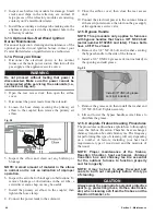
2. Hold fan so the oil locations are upright; then apply
10 drops of SAE 20 non-detergent oil (e.g., 3-IN-
ONE
®
Oil) in each location, as shown in Fig. 56.
Fig. 56
3. Install the combustion fan and secure with bolts.
3-12. Secondary Air Charge Tube and
Refractory
Removing and inspecting the secondary air charge
tube and inspecting the refractory is best done after the
outdoor furnace has been shut down and the firebox
has been cleaned according to the Complete Firebox
Cleaning Procedures.
NOTE: The secondary air charge tube and
refractory are wear items.
Fig. 57
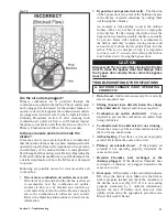
1. Remove the secondary air charge tube by lifting
and then sliding it toward the front of the outdoor
furnace. Inspect the mixing channel to see the area
is not plugged.
Summary of Contents for e-Classic 1450 IR
Page 17: ...15 Section 1 Outdoor Furnace Installation...
Page 29: ...27 Section 1 Outdoor Furnace Installation Fig 30 Fig 31...
Page 30: ...28 Section 1 Outdoor Furnace Installation Fig 32 Fig 33...
Page 66: ...64 E CLASSIC 1450 WIRING DIAGRAM Section 6 General Information...
Page 67: ...65 Section 6 General Information E CLASSIC 1450 WIRING DIAGRAM OPTIONAL POWER IGNITION...
Page 69: ...67 NOTES...
Page 70: ...68 NOTES...
Page 71: ...69 NOTES...

