


32
an impulsive controlled energy waveform with a resulting
constant detachment of melted material drops that reach
the workpiece without splatters. The welding cord is thus
well connected with any material type or thickness.
The welding parameter settings are the same as those
described for the synergic MIG/MAG welding.
9.2 MMA WELDING
For compact machines, connect the electrode clamp ca-
ble connector to connector
E
and the earth cable connec-
tor to connector
G
(observing the polarity stated by the
electrode manufacturer)
In case of machines with separate wire feeder the trolley
must remain connected to the power source.
Connect the electrode clamp cable connector to connec-
tor
X
and the earth cable clamp to connector
G
(observing
the polarity stated by the electrode manufacturer.
When this process is selected, after 5 seconds the power
source is ready to generate current.
In order to prepare the machine for MMA welding, follow
the instructions previously described in menu
“Wizard”
Par. 8.6 or “Par” 7.1
.
In menu
“Process Parameters”
the items that may be set
in this process are listed:
•
Hot Start.
It is the overvoltage supplied at the arc ignition time.
MIN
MAX
DEF.
Hot Start
0%
100%
50%
•
Arc Force.
It is the adjustment of the arc dynamic characteristic.
MIN
MAX
DEF.
Arc Force
0%
100%
30%
Display
D2
shows the arc voltage measured during weld-
ing.
Display
D1
shows:
- before welding, the current value set by means of
MI
;
- during welding, the measured welding current.
- When welding operation is completed, it shows the
most recent detected current value. (Led
L8
“HOLD”
on).
9.3 TIG WELDING
9.3.1. Only on machines with separate wire feeder.
Connect the earth cable to the positive pole
X
and the
power cable adaptor of the trolley/power source to the
negative pole
G
.
Connect the welding torch to the euro adapter
F
.
For this type of welding machines, the most suited weld-
ing torch is art.1259.
9.3.2 Compact machines.
Connect the earth cable to the positive pole
E
and the
torch to the negative pole
G
.
Connect the gas hose to the socket
H
In order to prepare the machine for TIG welding, follow the
instructions previously described in menu
“Wizard” Par.
8.6 or “Par” 7.1
.
In menu
“Process Parameters”
the items that may be set
in this process are listed:
•
Start Mode.
See paragraph 7.1.7.
•
Final Slope
(only in 2T or 4T).
It’s the time in seconds during which current slopes down
from welding to arc shutdown.
MIN
MAX
DEF
Final Slope
0.0 s
10 s
0.5 s
•
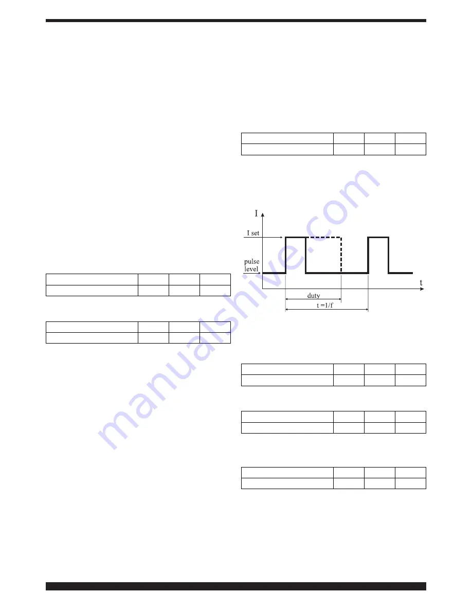
Pulse Art. 234 (optional)
Pulsed TIG welding.
In this type of welding, current intensity varies between
two levels; this variation occurs at a given frequency.
•
Pulse level
This item allows the setting of the lower current between
the two currents that are required for this welding pro-
cess; the percentage of this current is displayed accord-
ing to the main current set before entering the submenu.
MIN
MAX
DEF
Pulse level
1%
100%
50%
•
Frequency
It is the pulse frequency.
MIN
MAX
DEF
Frequency
0.1 Hz
500 Hz
1.1 Hz
•
Duty
This is the duration of the highest current, expressed in
percentage, compared to frequency time.
MIN
MAX
DEF
Duty
10%
90%
50%
Summary of Contents for EVO SPEED STAR 380 TC
Page 87: ...87...
Page 139: ...139...
Page 180: ...180 5 5 BA 6 6 7 7 3 4 F 8 8 BN BN CA CA BN CA BN D G 3 5 A 1683 ANT 318 319 9...
Page 181: ...181 9 M 3 6 3 6 1 3 7 IEC CEI EN 60974 9 G E F M B A D Q R H N T V S U W V Fig 10 L...
Page 195: ...195 Art 318...
Page 196: ...196 Art 319...
Page 197: ...197 Art 319...
Page 198: ...198 Art 320...
Page 199: ...199 Art 320...
Page 201: ...201 Art 318...
Page 203: ...203 Art 319...
Page 205: ...205 Art 320...
Page 207: ...207 Art 319 320...
Page 211: ...211...