


20
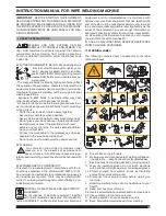
3.2 Welding sparks can cause fires. Have a fire extingui
-
sher nearby and have a watchperson ready to use it.
3.3 Do not weld on drums or any closed containers.
4 Arc rays can burn eyes and injure skin.
4.1 Wear hat and safety glasses. Use ear protection and
button shirt collar. Use welding helmet with correct
shade of filter. Wear complete body protection.
5 Become trained and read the instructions before
working on the machine or welding.
6 Do not remove or paint over (cover) label.
2 GENERAL DESCRIPTIONS
The equipment is a multi-process system suitable for
MIG/MAG welding, TIG (DC) welding with scratch start
and MMA welding (with the exception of cellulosic weld-
ing), developed with inverter technology. The equipment
may be used only for the purposes described in this man-
ual. The equipment must not be used to defrost pipes.
2.1 EXPLANATION OF TECHNICAL SPECIFICATIONS
This machine is manufactured according to the following
international standards:
IEC 60974-1 / IEC 60974-5 / IEC 60974-10 (CL. A) / IEC
61000-3-11 / IEC 61000-3-12 (see note 2).
No.
Serial number. Must be indicated on any re-
quest regarding the welding machine.
3~
f
1
f
2
Three-phase
static
transformer-rectifier
frequency converter.
MIG Suitable for MIG/MAG welding.
MMA Suitable for welding with covered electrodes.
TIG
Suitable for TIG welding.
U0.
Secondary open-circuit voltage.
X.
Duty cycle percentage.
The duty cycle expresses the percentage of
10 minutes during which the welding ma-
chine may run at a certain current without
overheating.
I2.
Welding current
U2.
Secondary voltage with I2 current
U1.
Rated supply voltage.
In the “Multi Voltage” models the machine
automatically adapts to the supply voltage
of the unit it is connected to.
3~ 50/60Hz Three-phase 50 or 50 Hz power supply.
I1 Max
Max. absorbed current at the corresponding
I2 current and U2 voltage.
I1 eff
This is the maximum value of the actual cur-
rent absorbed, considering the duty cycle.
This value usually corresponds to the capac-
ity of the fuse (delayed type) to be used as a
protection for the equipment.
IP23S
Protection rating for the housing. Grade
3
as the second digit means that this machine
may be stored, but it is not suitable for use
outdoors in the rain, unless it is protected.
S
Suitable for use in high-risk environments.
NOTES:
1- The equipment has also been designed for use in envi-
ronments with a pollution rating of 3. (See IEC 60664).
2- This equipment complies with a IEC 61000-3-12 stan-
dard provided that the allowed maximum impedance
Zmax of the unit is lower or equal to 0.090 (Art. 318
and 319)-0.051 (Art. 320) at the interface point between
the user unit and the mains. The fitter or the unit user
are responsible for connecting the unit to a power sup-
ply with a maximum allowed system impedance Zmax)
lower or equal to 0.090 (Art. 318 and 319)-0.051 (Art.
320).
3 INSTALLATION AND ASSEMBLY
.
3.1 LIFTING MECHANISM
(FIG. 1).
Fig. 1
3.2 ASSEMBLY
• All power sources must be fitted with axle and then rear
wheels (fig. 2) .
Fig. 2
• For machines with trolley, the pivoting system must
be mounted both on the wire feeder trolleys and the
power source; the small wheels provided together with
the screws must be mounted at the bottom of the wire
feeder trolley as well as the welding torch support, then
place the trolley in its position. (
see figure 3
).
Summary of Contents for EVO SPEED STAR 380 TC
Page 87: ...87...
Page 139: ...139...
Page 180: ...180 5 5 BA 6 6 7 7 3 4 F 8 8 BN BN CA CA BN CA BN D G 3 5 A 1683 ANT 318 319 9...
Page 181: ...181 9 M 3 6 3 6 1 3 7 IEC CEI EN 60974 9 G E F M B A D Q R H N T V S U W V Fig 10 L...
Page 195: ...195 Art 318...
Page 196: ...196 Art 319...
Page 197: ...197 Art 319...
Page 198: ...198 Art 320...
Page 199: ...199 Art 320...
Page 201: ...201 Art 318...
Page 203: ...203 Art 319...
Page 205: ...205 Art 320...
Page 207: ...207 Art 319 320...
Page 211: ...211...