


70
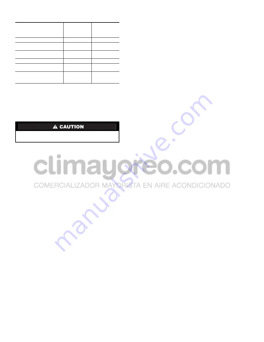
Table 43 — Replacement Module Part Number
Refer to the Start-Up Checklist for 30GXN,GXR,HX
Liquid Chillers (completed at time of original start-up) found
in the job folder. This information is needed later in this
procedure. If the checklist does not exist, fill out the current
information in the Configuration mode on a new checklist.
Tailor the various options and configurations as needed for this
particular installation.
1. Check that all power to unit is off. Carefully disconnect
all wires from the defective module by unplugging its
connectors. Remove the screw securing the communica-
tion drain wire (CCP modules only). Save the screws.
2. Remove the defective module by removing its mounting
screws with a Phillips screwdriver, and removing the
module from the control box. Save the screws later use.
For Navigator replacement, remove the screw securing
the cable clamp near TB3.
3. Verify that the instance jumper (MBB) or address
switches (all other modules) exactly match the settings of
the defective module.
4. Package the defective module in the carton of the new
module for return to Carrier.
5. Mount the new module in the unit’s control box using a
Phillips screwdriver and the screws saved in Step 2.
6. Reinstall all module connectors and communication
drain wire (CCP modules only). For Navigator replace-
ment, make sure the plug is installed at TB3 in the LEN
connector.
7. Carefully check all wiring connections before restoring
power.
8. Verify the Enable/Off/Remote Contact switch is in the
OFF position.
9. Restore control power. Verify that all module red LEDs
blink in unison. Verify that all green LEDs are blinking
and that the Navigator is communicating correctly.
10. Verify all configuration information, settings, setpoints
and schedules. Return the Enable/Off/Remote Contact
switch to normal operation position.
Winter Shutdown Preparation —
At the end of
each cooling season the fluid should be drained from the
system. However, due to the cooler circuiting, some fluid will
remain in the cooler after draining. To prevent freeze-up
damage to the cooler tubes perform the following procedure.
1. If cooler heaters have been installed, deenergize the
heaters to prevent damage and possible safety hazards
when draining, or when there is no liquid in the system.
Remove Fuse 1 to deenergize the heaters. Drain the fluid
from the system.
2. Isolate the cooler from the rest of the system with water
shut off valves.
3. Completely fill the cooler with an appropriate amount of
inhibited ethylene glycol solution (or other suitable
corrosion-inhibitive antifreeze) for 15
°
F (8.3
°
C) below
the expected low ambient conditions (5 gallon [19 L]
minimum).
4. Leave the cooler filled with the antifreeze solution for the
winter, or drain if desired. Be sure to deenergize heaters
(if installed) as explained in Step 1 to prevent damage.
Use an approved method of disposal when removing the
antifreeze solution.
5. Update item W.DNE
Winterization Performed
(Configu-
ration Mode, Sub-mode SERV) to YES. Winterization is
complete.
Maintenance
RECOMMENDED MAINTENANCE SCHEDULE — The
following are only recommended guidelines. Job site condi-
tions may dictate that maintenance schedules be performed
more frequently than listed here.
ROUTINE (as conditions dictate)
30GX machines with E-coat condenser coils:
•
Check condenser coils for debris, clean as necessary
•
Periodic clean water rinse, especially in coastal and
industrial applications.
MONTHLY
30GX machines with E-coat Condenser Coils:
•
Check condenser coils for debris, clean as necessary
•
Coil cleaning with Carrier approved coil cleaner.
EVERY 3 MONTHS
All machines:
•
Check all refrigerant joints and valves for refrigerant
leaks, repair as necessary.
•
Check moisture indicating sight glass for possible refrig-
erant loss and presence of moisture.
•
Check oil filter pressure drops, replace as necessary.
•
Check chilled water flow switch operation.
30GX machines:
•
Check condenser coils for debris, clean as necessary.
•
Check condenser fan operation.
YEARLY:
All machines:
•
Check all electrical connections. Tighten as necessary.
•
Check accuracy of all transducers for each circuit,
replace as necessary.
•
Check accuracy of thermistors, replace if greater than
± 2° F (1.2° C) variance from calibrated thermometer.
•
Obtain and test an oil sample, change as necessary.
•
Clean cooler tubes if appropriate.
•
Check to be sure that the proper concentration of
antifreeze is present in the chilled water loop.
•
Check to be sure that the proper amount of inhibitor is
present in the chilled water loop.
•
Check all refrigerant strainers and filter driers for
pressure drops, replace/clean as necessary
•
Check chilled water strainers, clean as necessary
30GX machines:
•
Check cooler heater operation
•
Check condenser fan blades to insure they are securely
fastened to the motor shaft and their condition.
MODULE
REPLACEMENT
PART NUMBER
(With Software)
REPLACEMENT
PART NUMBER
(Without
Software)
Main Base Board (MBB)
30GX506748
HK50AA029
Expansion Valve Board
(EXV)
30HX515217
HK50AA026
Screw Compressor
Board (SCB)
30HX501316
HK50AA032
Navigator Display
HK50AA033
N/A
Energy Management
Module (EMM)
30HX515218
HK50AA028
Comfort
Link™ Compressor
Protection Boards
(CCP1, CCP2)
HN67LM103
N/A
Electrical shock can cause personal injury. Disconnect all
electrical power before servicing.


